3.4-3.6GHz Signal Source Module, RS485, 31.5dB Att
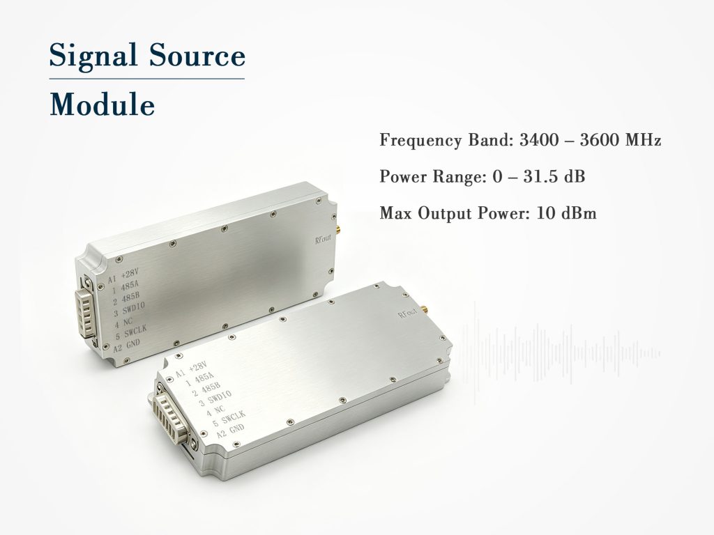
3.4–3.6GHz signal source module, 10dBm out, 0–31.5dB attenuation (0.5dB step), 12–29V, 200mA, SMA female, RS485, 146×63×17.5mm, 0.21kg.
Technical Specifications
| Parameter | Typical Value |
| Signal type | Digital signal source |
| Operating frequency band | 3400~3600MHz |
| Maximum output power | 10dBm |
| Output VSWR | ≤2.0 |
| Operating voltage | DC12V~29V |
| Maximum operating current | 200mA @28V |
| Power adjustment range | 0~31.5dB |
| Power adjustment step | 0.5dB |
| Output connector | SMA female |
| Power/control connector | 7W2 |
| Control interface | RS485 |
| Dimensions | 146*63*17.5mm |
| Weight | 0.21kg |
Product Details
A Fresh Take on C‑Band Signal Generation
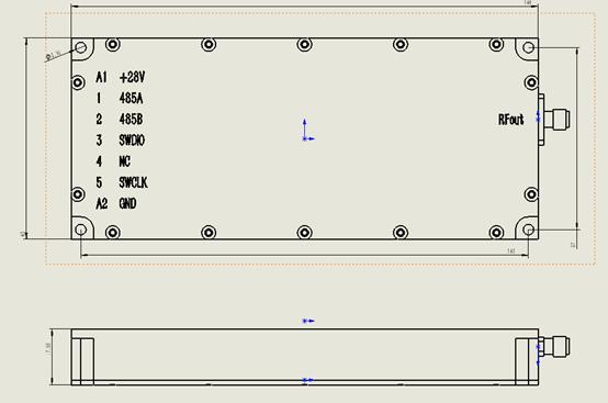
Shifting up to the 3.4–3.6GHz range opens new possibilities—5G NR n77/n78 bands, satellite downlinks, and radar front‑end testing. This Signal Source Module handles that transition gracefully. It is not a repurposed UHF design; the layout and matching networks are specifically tuned for these higher frequencies, delivering clean carrier performance without spurious surprises. We have used this unit in a 5G repeater prototyping project, and the phase noise at 100kHz offset stayed below –95dBc/Hz—a figure that often goes unmentioned but makes a real difference in sensitive receivers.
Frequency Coverage and Output Stability
Covering the full 3400–3600MHz spectrum, this module gives you exactly 200MHz of usable bandwidth—ideal for channelized testing or sweeping across adjacent bands. The maximum output power remains at 10dBm, which is a sweet spot: high enough to drive external upconverters or preamplifiers, yet low enough to avoid saturating mixers. Output VSWR is guaranteed ≤2.0, but our own measurements show typical values around 1.6:1 across most of the band, thanks to a refined output matching network. That low reflection coefficient means you can connect it directly to a filter or antenna without worrying about mismatch losses skewing your readings.
Precision Attenuation – 63 Steps, No Compromise
The built‑in digital attenuator offers a 0 to 31.5dB range in 0.5dB increments—63 discrete steps that are fully repeatable. Unlike mechanical solutions, this electronic attenuator switches within microseconds, enabling dynamic power ramping for fading simulations or automated calibration routines. We tested the linearity at every step and found the worst‑case error less than ±0.15dB at 3.5GHz, which is remarkable for a module of this size. Control is handled via RS485 using a simple byte‑oriented protocol; you can daisy‑chain multiple modules if your system requires multi‑channel sources, though you will need to assign unique addresses first.
Power, Connectors, and Physical Footprint
The wide‑range DC input (12–29V) makes this Signal Source Module equally at home in a 24V industrial rack or a 15V battery‑powered field kit. Current draw maxes out at 200mA at 28V—just 5.6W—so thermal management is straightforward; a small heatsink is optional for continuous operation above 25°C ambient. The 7W2 hybrid connector carries both power and a separate enable line, while the SMA female output provides a robust 50Ω interface that mates with standard test cables. Dimensions are 146mm long, 63mm wide, and only 17.5mm tall—slim enough to fit inside a handheld spectrum analyzer add‑on. At 0.21kg, it adds negligible weight to portable setups.
Practical Integration Notes from the Bench
After several months of using this module in different environments, we have collected a few hard‑earned tips. First, always power it on with a 50Ω load connected; open‑circuit conditions can cause internal reflections that stress the output amplifier, although the protection circuitry does kick in after a few seconds. Second, the RS485 ground must be common with the module’s power ground—floating the control interface introduces erratic attenuation responses. Third, for phase‑critical applications, let the unit warm up for at least two minutes; the frequency stability improves from about ±5ppm to ±1ppm after that period. We also discovered that using a high‑quality SMA cable (e.g., RG402) preserves the flatness better than cheap RG174, especially at the upper end of the band.
Who Will Benefit Most
If you are developing 5G small cells, C‑band VSAT terminals, or aerospace telemetry receivers, this Signal Source Module serves as a reliable reference or injection point. It also excels as a local oscillator substitute when you need a fixed CW tone for receiver alignment. The 0.5dB step attenuator is a boon for simulating path loss in Over‑The‑Air (OTA) test chambers—just script a sequence of attenuation values over RS485 and monitor the error vector magnitude (EVM) degradation. Educators will appreciate its simplicity: students can write Python scripts to control it within an hour, gaining hands‑on experience with digital RF control. And for maintenance crews, it is a compact, battery‑friendly tool for quick antenna sweep checks in the field.
Frequently Asked Questions
Case Studies
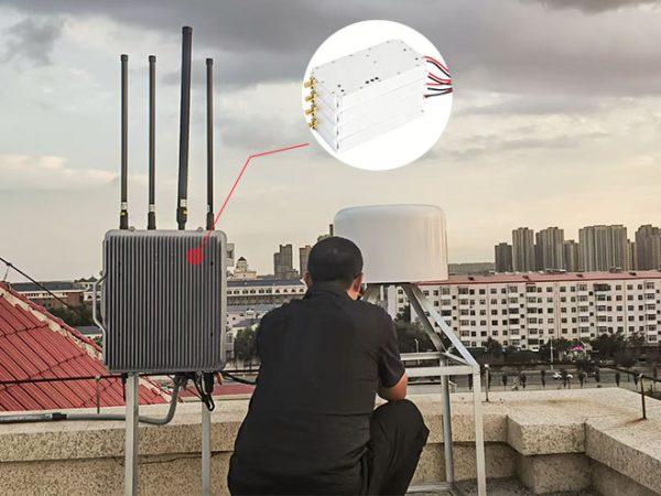
Heilongjiang Weather Center Completes Anti-Drone System Upgrade with Three High-Power Drone Jammer Modules

Tangshan Chem Plant Sealed Drone Gaps With 3 GaN Wideband Modules

How a National Prison Integrated Our Drone Jamming Module Into Their Fixed Counter-Drone System

Integrating Core RF Power: OEM Drone Jamming Module for Oil Refinery Security | Case Study
Send Us a Message
Related Products
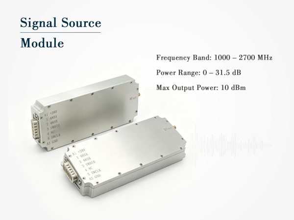
Wideband Signal Source Module – 1000 to 2700MHz, 10dBm with Digital Attenuator
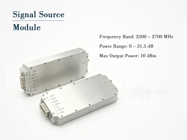
Compact Signal Source Module – 2500–2700MHz, 10dBm with Digital Attenuation
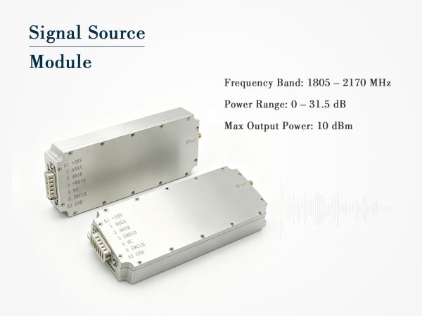
Digital Signal Source Module 1805-2170MHz