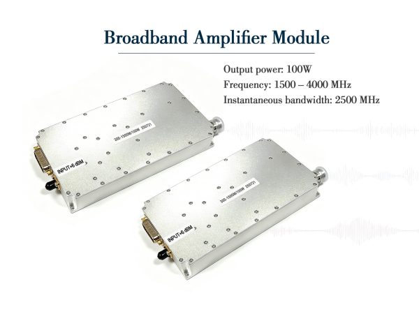
100W Broadband Amp Module – 20 to 600 MHz Wideband Power for HF/VHF/UHF
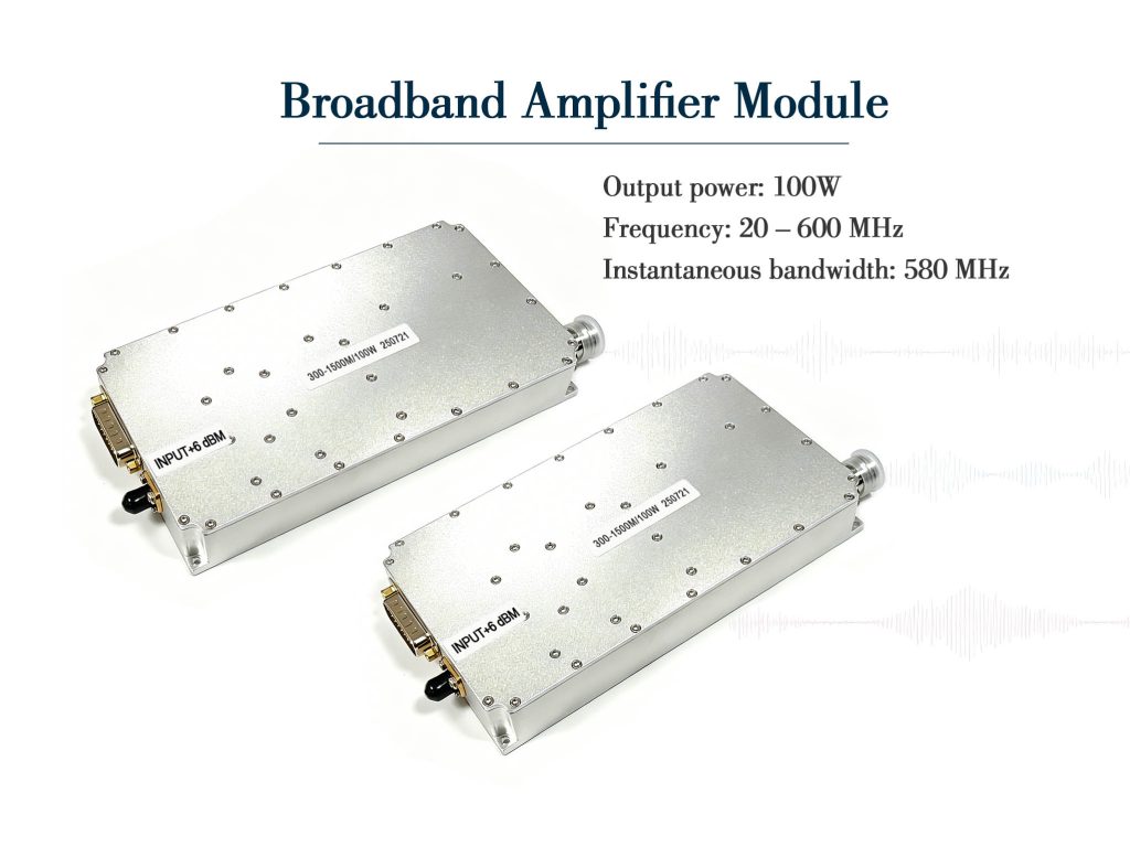
100W broadband amp module, 20–600 MHz, 50±3 dB gain, 32% efficiency, 28-32V, 0.75kg, rugged GaN design for HF/VHF/UHF.
It works as a final stage for HF/VHF transceivers, as a booster for UHF data links, and as a laboratory driver for antenna testing and EMC measurements. The instantaneous bandwidth supports frequency‑hopping waveforms without re‑tuning, so you can sweep through the entire range during characterisation without stopping to adjust bias or matching.
Technical Specifications
| Parameter | Value |
| Frequency range | 20 – 600 MHz |
| Instantaneous bandwidth | 580 MHz (typical) |
| Peak output power (CW) | 100 W (typical) |
| Input drive power | -2 ±3 dBm (typical) |
| Max input without damage | 5 dBm |
| Power gain (at 0 dBm in) | 50 ±3 dB (typical) |
| Gain flatness | ±3 dB (max, full band) |
| Efficiency | 32% (typical, better at lower end) |
| Harmonics @100W | ≥10 dBc |
| Spurious level | ≥60 dBc |
| Input / Output VSWR | ≤2:1 |
| Operating voltage | 28 – 32 VDC |
| Current @100W | 10 A (typical) |
| Mass | 0.75 kg |
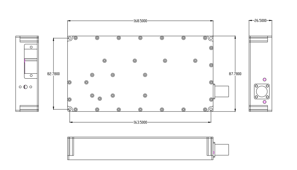
| Dimensions | 168.5 × 82.8 × 26.5 mm |
Product Details
Low-frequency bands from 20 MHz up to 600 MHz cover a huge territory – from HF communications through VHF and into UHF. Many amplifiers handle either the lower end or the higher end, but few deliver a clean 100 watts across the entire span without band switching. This broadband amp module changes that. It gives you a full 580 MHz of instantaneous bandwidth, so you can cover legacy tactical radios, amateur bands, and commercial LMR systems with one single unit.
Core Technology: GaN on SiC
Inside the housing sits a Class AB GaN die on a silicon carbide substrate. That combination is particularly effective at lower frequencies because it offers low thermal resistance and high breakdown voltage. The die mounts onto a copper sub‑carrier, and a patented thermal spreader pulls heat away from the active junction. Even with the baseplate at 50°C, the module holds its rated output – a critical feature for base stations and repeater shelters where ambient temperatures rise quickly.
Electrical Performance at a Glance
Running from a 28–32V DC supply (a slightly wider range than our higher‑band models), this amp delivers 100 W CW typical at peak output. Current draw sits around 10 A at full tilt, which is reasonable for a 100‑watt brick. Small‑signal gain is 50 ±3 dB when driven with 0 dBm, and gain flatness stays within ±3 dB over the whole 20–600 MHz window. That flatness saves you from adding external slope equalisers. Harmonics are better than 10 dBc at full power, and spurious outputs are suppressed by at least 60 dBc – a clean enough spectrum for most transmitter chains.
Input and output VSWR are both specified at ≤2:1 into 50 ohms, so you can drop this module directly after a driver stage or before an antenna feed without worrying about mismatches. The maximum input power without damage is 5 dBm, but for best linearity we suggest staying within the typical -2 ±3 dBm drive range.
Compact and Lightweight Build
Physically, this module shares the same footprint as its higher‑frequency siblings: 168.5 × 82.8 × 26.5 mm and just 0.75 kg. That consistency means you can use the same mechanical mounting brackets and cooling designs across multiple band versions. The aluminium housing is machined with a corrosion‑resistant finish, and internal components are encapsulated to resist vibration and humidity – a plus for mobile or shipboard installations.
Where This Broadband Amp Module Shines
Because it covers 20–600 MHz, this broadband amp module fits perfectly in multi‑mission communication systems. It works as a final stage for HF/VHF transceivers, as a booster for UHF data links, and as a laboratory driver for antenna testing and EMC measurements. The instantaneous bandwidth supports frequency‑hopping waveforms without re‑tuning, so you can sweep through the entire range during characterisation without stopping to adjust bias or matching.
Thermal and Efficiency Notes
Efficiency is rated at 32% typical – slightly better than our 6–8 GHz model because lower frequencies have lower switching and conduction losses. At 100 W output, that means about 68 W of heat to dissipate, so a decent heatsink with forced air is recommended for continuous CW operation. The module can handle a 50°C baseplate, but active cooling extends component life and keeps gain stable over long run times.
Installation Tips for Best Results
Place the module as close to the output connector as possible to minimise cable losses. Use high‑quality 50‑ohm coax with low insertion loss, especially at the upper end near 600 MHz. Bypass the DC feed with a low‑ESR capacitor close to the power pin to avoid low‑frequency oscillations. Also, if you are driving the amp with a high‑power exciter, add a 3‑dB pad on the input to protect against accidental overdrive – the 5‑dBm maximum is not a hard limit, but exceeding it repeatedly may degrade the front end.
What Sets It Apart
Many competing broadband amps in this power class use LDMOS, which loses gain at higher frequencies and runs hotter. GaN gives you flatter gain, higher ruggedness, and better thermal headroom. Also, the extended 28–32V supply range makes this module compatible with battery systems that may sag under load. The wide bandwidth means you do not need separate amps for HF, VHF, and UHF – one module replaces three narrowband units.
Final Take
If your system requires 100 watts of clean, flat power from 20 to 600 MHz without compromises, this broadband amp module is a straightforward choice. It is not the cheapest option, but the combination of bandwidth, gain flatness, and mechanical ruggedness reduces integration overhead and improves overall reliability. For engineers who want a single amplifier to cover a broad swath of low‑VHF to high‑UHF, this unit delivers.
Frequently Asked Questions
Case Studies
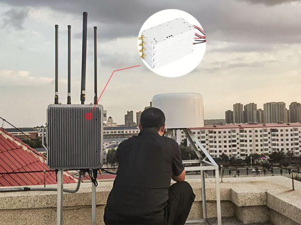
Heilongjiang Weather Center Completes Anti-Drone System Upgrade with Three High-Power Drone Jammer Modules

Tangshan Chem Plant Sealed Drone Gaps With 3 GaN Wideband Modules

How a National Prison Integrated Our Drone Jamming Module Into Their Fixed Counter-Drone System

Integrating Core RF Power: OEM Drone Jamming Module for Oil Refinery Security | Case Study
Send Us a Message
Related Products
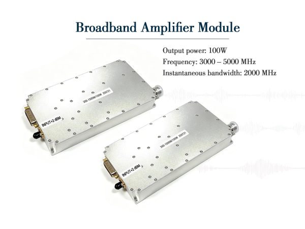
High-Power 100W GaN Broadband Amplifier Module 3-5 GHz
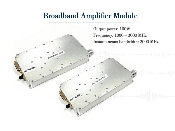
100W GaN Broadband Amplifier Module 1–3 GHz

100W Broadband Amplifier Module – 6 to 8 GHz Wideband Power