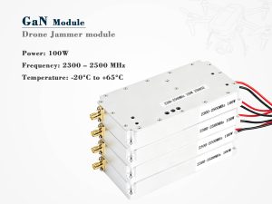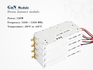
Important: RF jamming is tightly regulated in most countries. This article is intended for authorized RF engineers, integrators, test teams, and compliance professionals. Do not deploy jamming equipment without valid legal authorization.
In counter-drone RF systems, VSWR is often treated as an antenna parameter rather than a module parameter. That assumption is costly. A drone jammer module may deliver excellent output power on a test bench, yet lose range, overheat, or trigger protection once it is connected to a real antenna on a vehicle, mast, backpack, or airframe.
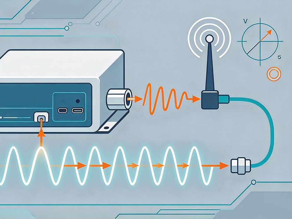
VSWR is the bridge between the power a module generates and the power an antenna actually radiates. When that bridge is weak, the system pays for it in heat, reflected energy, reduced range, and unreliable field performance.
1. What VSWR Really Tells You
VSWR describes how well the RF load matches the source impedance. In a 50-ohm system, a perfect match is 1.0:1. In practice, no broadband jammer module achieves a perfect match across every frequency and operating condition.
The key issue is reflected power. As VSWR rises, more energy returns to the power amplifier. That energy becomes heat, stress, and potential failure.
| VSWR | Return Loss | Reflected Power | Practical Effect |
|---|---|---|---|
| 1.2:1 | 20.8 dB | 0.8% | Excellent margin |
| 1.5:1 | 14.0 dB | 4.0% | Common design target |
| 2.0:1 | 9.5 dB | 11.1% | Usable, but heat rises |
| 2.5:1 | 7.4 dB | 18.4% | Derating or protection needed |
| 3.0:1 | 6.0 dB | 25.0% | High risk of instability |
| 5.0:1 | 3.5 dB | 44.4% | PA damage is likely |
A module rated for 100 W may radiate far less than 100 W if VSWR is poor. Worse, the reflected power does not disappear. It returns to the final stage, where it can reduce efficiency, increase junction temperature, and shorten component life.
2. Why Drone Jammer Modules Are More Sensitive
Drone jammer modules are not ordinary transmitters. They often combine several challenging requirements:
-
Wide frequency coverage
-
High output power in a compact enclosure
-
Multiple bands and ports
-
Broadband antennas
-
Close integration with metal structures
-
Continuous or high-duty-cycle operation
-
Strict size, weight, and power limits
Each factor can push VSWR away from the ideal. A design that performs well on a laboratory bench may behave differently when the antenna is mounted near a vehicle roof, carbon-fiber frame, or operator’s body.
3. Target VSWR by Frequency
There is no single VSWR target for every drone jammer module. The acceptable value depends on band, power level, antenna type, duty cycle, and thermal design.
| Band | Typical Role | Design Target | Integration Caution |
|---|---|---|---|
| 433 MHz | Remote control, telemetry | ≤2.0:1, prefer ≤1.5:1 | Large antenna, mounting effects |
| 868/915 MHz | Remote control, telemetry | ≤2.0:1 | Regional band differences |
| 1.2 GHz | Video, telemetry | ≤2.0:1 | Cable loss and connector quality |
| 1.5 GHz | GNSS-related testing | ≤1.5:1 | Filter and out-of-band sensitivity |
| 2.4 GHz | Remote control, video | ≤2.0:1 | Broadband matching, PCB parasitics |
| 5.8 GHz | Video | ≤2.0:1 | Small geometry, connector repeatability |
For high-power modules, a tighter target is usually wise. A 1.5:1 limit at the module port gives more margin for antenna mismatch, cable aging, water ingress, and mechanical variation.
4. Design Choices That Keep VSWR Under Control
Good VSWR performance is not achieved by a single component. It comes from disciplined RF design.
Broadband matching matters more than a single sweet spot.
A narrow match at the center frequency is not enough. The band edges often determine whether the module remains stable.
Isolators and circulators protect the PA, but they are not a cure.
They add insertion loss, cost, size, and heat. They can improve reliability, but they should not replace a proper matching network.
Cable and connector quality cannot be ignored.
At 2.4 GHz and 5.8 GHz, a poor connector, damaged cable, or incorrect torque can change VSWR significantly.
Thermal drift changes impedance.
As the PA heats, matching components and PCB materials can shift. A design that is stable when cold may drift when hot.
Antenna placement is part of the RF circuit.
Metal nearby, ground plane size, cable routing, and enclosure materials all affect the match. The module port is not the end of the story.
5. A Practical Test Sequence
Use a sequence that reflects real operating conditions, not just laboratory convenience.
-
Confirm legal authorization and test area approval.
-
Calibrate the vector network analyzer at the module connector.
-
Sweep every band and every operating mode.
-
Record S11 and VSWR curves, not just a single number.
-
Test at rated power using a directional coupler.
-
Repeat the test with the actual antenna installed on a representative platform.
-
Add temperature, vibration, and sealing tests, then repeat VSWR checks.
-
Document the worst-case frequency, VSWR, power, and temperature.
Never operate a high-power amplifier without a suitable load or approved antenna. Open ports and incorrect loads can cause immediate reflected-power damage.
6. How to Read a Supplier Datasheet
Many datasheets look better than the product performs because they omit test conditions. Use the following table when evaluating a supplier.
| Datasheet Claim | Ask For | Warning Sign |
|---|---|---|
| “Low VSWR” | Full sweep and worst-case frequency | One frequency point only |
| “High power” | VSWR at rated power and temperature | Cold small-signal data only |
| “Wideband” | VSWR at band edges | Mid-band data only |
| “Protected” | Reflection detection, ALC, thermal cutoff | No protection details |
| “Integration ready” | Installed-antenna test data | Module-only data only |
A credible supplier will provide test conditions, connector type, cable type, load, temperature, and the exact frequency of worst-case VSWR.
7. Procurement Checklist
| Area | Requirement |
|---|---|
| RF data | S11/VSWR curves for all bands, ports, and power levels |
| Test conditions | Temperature, cable, connector, load, and calibration details |
| Protection | Reflected-power detection, ALC, over-temperature shutdown |
| Mechanical | Connector torque, sealing, vibration, and shock ratings |
| Compliance | Legal authorization, certification, and documentation |
| Support | Integration notes and field troubleshooting guidance |
Final Take
Drone jammer module VSWR is not a minor datasheet detail. It directly affects radiated power, thermal stress, protection behavior, and real-world range. A module with moderate output power and excellent VSWR can outperform a higher-power module with poor matching.
For RF designers, the goal is not a perfect VSWR curve on paper. The goal is stable, repeatable performance after the module is installed on the actual platform. For procurement teams, the goal is not a bold power rating. The goal is verified RF data under realistic conditions.