
8–12 GHz 100 W GaN Amplifier Module for EMC and Test
8–12 GHz GaN amplifier module: 100 W PSAT, 50 dB gain, 28 VDC, 50 Ω, over-temperature/current protection, SMA input and N-K output.

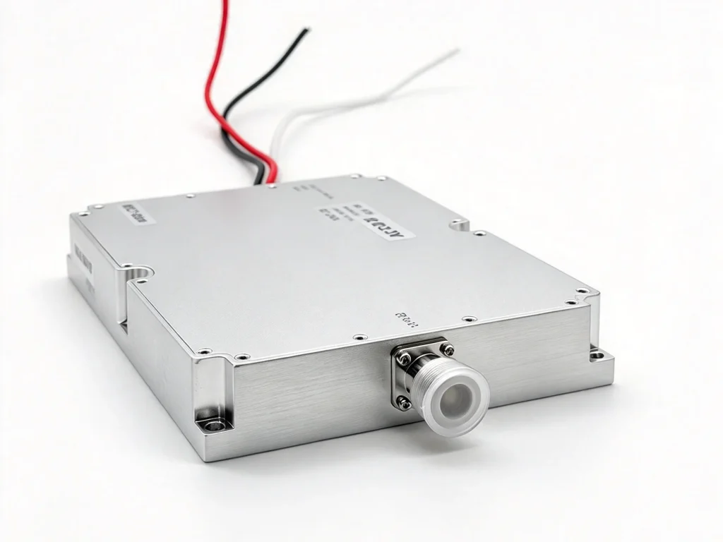
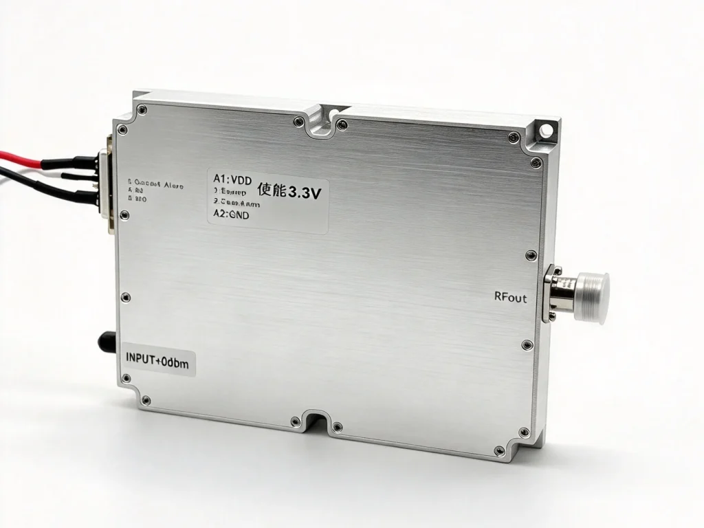
Technical Specifications
| Parameter | Specification | Notes |
| Frequency range | 8000–12000 MHz | Operating band; electrical table min/max 7800–12300 MHz |
| Output power | 100 W typical PSAT | 49.5 W min / 50.5 W max at PSAT, +28 VDC, 25°C, Pin=0 dBm, 50 Ω |
| Supply voltage | 28 VDC | Operating voltage |
| Current draw | 8 A quiescent; 15.5 A at 50 W | Over-current shutdown above 20 A |
| Modulation source | External RF input | No internal modulator described in datasheet |
| Analog scan speed | N/A | Not a specified function of this amplifier |
| Input / output impedance | 50 Ω | Input and output matched |
| Protection LEDs | Temperature/current alarm outputs, LVTTL 0/+3.3 V | No dedicated LED listed; alarm status via pins |
| Operating temperature | -20°C to +50°C | Non-operating -25°C to +65°C; humidity 95% non-condensing |
| Dimensions (L×W×H) | 160 × 120 × 25 mm | 6.30 × 4.72 × 0.98 in maximum |
| Weight | 1.0 kg | 2.2 lb maximum |
| Base material | GaN devices with chip-and-wire construction | Housing material not stated |
Product Details
The GaN Amplifier Module is a multi-octave GaN power amplifier for 8–12 GHz. It delivers 100 W typical saturated output power from a 160 × 120 × 25 mm housing. The target is straightforward: broadband coverage with enough margin for EMC, jamming, and test benches. GaN devices and chip-and-wire construction keep power density high without adding bulk. Input and output are matched to 50 Ω, so integration is mostly a matter of DC, RF, and cooling.
Broadband RF performance
Across 8–12 GHz, power gain at PSAT is about 50 dB with ±1 dB flatness. Input return loss is -10 dB. Harmonics are -50 dBc at 100 W, and spurious signals are -60 dBc at PSAT. The datasheet curve plots output power, DC current, and PAE at room temperature with Pin = 0 dBm. At 28 VDC, quiescent current is 8 A. Dynamic current is 15.5 A at 50 W, and power-added efficiency is 22–30%. The electrical table gives 7800–12300 MHz min/max and 49.5–50.5 W min/max at PSAT, so unit-to-unit spread is tight. This is useful when one amplifier must cover several bands without retuning.
Protection and control
The enable pin accepts TTL logic high (3.3 V) and is internally pulled low. The enable line is pulled low internally, so a high level is required to turn the amplifier on. The temperature alarm is LVTTL 0/+3.3 V: 0 V means normal, +3.3 V means above +85°C. Above +85°C the GaN Amplifier Module shuts down; below +65°C it turns on again. The current alarm is also LVTTL 0/+3.3 V. When current exceeds 20 A, the module shuts down and stays off until the user repowers it. These alarm pins are easy to wire to a system controller.
Mechanical and interface notes
RF input is SMA female; RF output is N-K female. DC and control use a hybrid 7W2 mixed-contact D-sub male connector. The DC interface uses A1 for VDD, A2 for ground, pin 1 for enable, pin 2 for temperature alarm, pin 3 for current alarm, pin 4 for NC, and pin 5 for ground. The housing has six Ø4.2 mm through-holes. Maximum weight is 1.0 kg. Operating temperature is -20°C to +50°C; non-operating is -25°C to +65°C, with 95% non-condensing humidity. The absolute maximum RF drive without damage is +10 dBm. At 100 W output, the load can see 5:1 VSWR across all phase and amplitude conditions. Thermal shutdown is 85°C ±5°C.
Where it fits
This is a practical GaN Amplifier Module for EMC rooms, lab benches, and system integrators that need 8–12 GHz coverage at 100 W class. It is not a narrowband replacement; the value is the wide instantaneous band, 50 Ω match, and built-in protection. Use a clean 28 VDC supply, respect the 20 A current limit, and keep airflow over the housing. For bench use, start at Pin = 0 dBm and check the alarm lines before full drive. Drive it from an external RF source; there is no internal modulator. Keep the load within 5:1 VSWR, because protection may trip outside that range. The alarm outputs can report status to a controller. With proper mounting and thermal design, the module supports repeated high-power testing and jamming tasks.
Frequently Asked Questions
Case Studies
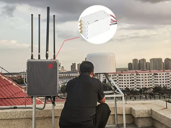
Heilongjiang Weather Center Completes Anti-Drone System Upgrade with Three High-Power Drone Jammer Modules

Tangshan Chem Plant Sealed Drone Gaps With 3 GaN Wideband Modules

How a National Prison Integrated Our Drone Jamming Module Into Their Fixed Counter-Drone System

Integrating Core RF Power: OEM Drone Jamming Module for Oil Refinery Security | Case Study
Send Us a Message
Related Products

10–13 GHz 100W GaN Jammer Module for EMC & Test

High-Power 100W GaN Broadband Amplifier Module 3-5 GHz

100W GaN Broadband Amplifier Module 1–3 GHz