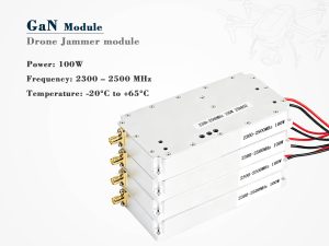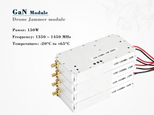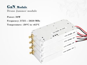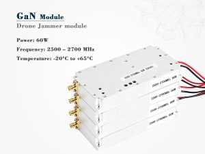
Drone jammer module troubleshooting starts with one rule: verify the symptom before replacing parts. A jammer module may fail because of power, heat, antenna mismatch, firmware, or band settings. This guide walks through practical checks that technicians can run in a workshop or field test. It also explains when the issue is not the module at all.
Symptom-to-Cause Map
Use the table below to narrow the fault. Do not skip basic measurements. Many “dead” modules simply have a blown fuse, a loose coax, or a disabled band.
| Symptom | Likely cause | First check |
|---|---|---|
| No output on any band | Power supply or fuse | DC voltage and current draw |
| Weak output on one band | Damaged amplifier or filter | Gain and return loss |
| Overheating after minutes | Poor airflow or high duty cycle | Fan, heatsink, thermal paste |
| Drone link survives | Wrong band or low ERP | Frequency plan and antenna gain |
| Random shutdowns | Voltage sag or firmware bug | Load test and logs |
Power and Heat
Start with the power supply. Measure voltage under load, not just at idle. A supply that reads 12 V open-circuit may drop below 10 V when the amplifier transmits. Check connectors, fuses, and wiring gauge. Then inspect heat. GaN and LDMOS amplifiers lose efficiency as temperature rises. Clean dust from heatsinks, confirm fan direction, and replace dried thermal paste. If the module has a duty-cycle setting, reduce it during diagnosis.
RF Chain and Antenna Checks
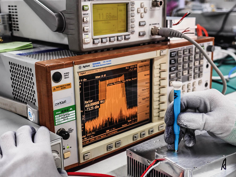
Drone jammer module troubleshooting for RF problems should follow the signal path: source, driver, amplifier, filter, and antenna. Use a spectrum analyzer or power meter. A high SWR often means a damaged coax, water ingress, or a wrong connector torque. Directional antennas must point at the target area; a misaligned panel can make a working module look weak. For integrated systems, the drone detection system may send a false trigger, so verify cueing data before blaming the jammer.
| RF check | Tool | Pass condition |
|---|---|---|
| Output power | Power meter | Within 10% of spec |
| Frequency error | Spectrum analyzer | Inside allowed band |
| Return loss | VNA or SWR meter | Better than -10 dB |
| Cable loss | VNA | Matches cable datasheet |
External reference: FCC jamming guidance. Also see ITU radio regulations.
Control, Firmware, and Band Settings
Drone jammer module troubleshooting for control issues often points to software. Confirm that the correct band is enabled. Check frequency lists against the drone protocol. Update firmware only from a trusted source, and back up settings first. Review logs for over-temperature, VSWR trip, or low-voltage events. If the module uses an SDR, verify sample rate and gain. A wrong gain setting can create harmonics that trigger protection circuits.
Environmental and Legal Checks
Water, dust, and vibration damage connectors and PCBs. Use conformal coating and gaskets in outdoor enclosures. Cold temperatures can shift oscillator performance, while direct sun raises internal heat. Finally, confirm legal limits. Civilian jamming is restricted in many countries. Test in a shielded room or with proper authorization. For maintenance schedules, see our how does a drone jammer module work.
FAQ
Q: Why does the module power on but not jam?
Check band enable, antenna connection, and output power.
Q: Why does it shut down after a few minutes?
Heat, voltage sag, or VSWR protection are common causes.
Q: Can firmware fix weak output?
Rarely. Firmware controls settings, not amplifier hardware.
Drone jammer module troubleshooting is a process of elimination. Verify power, manage heat, test the RF chain, confirm settings, and respect the law. With a logical workflow, most faults can be traced without guesswork.