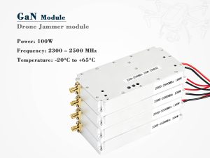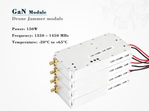
A broadband amplifier module is often drawn as a simple “gain block” on a system diagram. In reality, it is a packaged RF/microwave assembly that must maintain gain, noise performance, linearity, and stability over a frequency range that may cover several octaves. That wide coverage is what separates a broadband module from a narrowband amplifier tuned to one specific band.

Broadband amplifier modules are used in test instruments, radar, electronic warfare, satellite communications, 5G infrastructure, EMC testing, and receive/transmit chains where signals may appear across a wide spectrum.
What Makes an Amplifier “Broadband”?
“Broadband” is relative. In RF engineering, bandwidth may be described as an absolute range, such as 10 MHz to 6 GHz, or as a ratio, such as 2:1 or 10:1. A module covering one octave is usually considered wideband. Multi-octave and decade-bandwidth designs are common in instrumentation and defense systems.
The trade-off is important: wider bandwidth often means lower gain per stage, higher noise figure, or lower output power compared with a narrowband design optimized for a single band.
| Class | Typical ratio | Example range | Common use |
|---|---|---|---|
| Narrowband | <10% | 2.4–2.5 GHz | Wi-Fi front end |
| Wideband | About one octave | 2–4 GHz | Radar, satcom |
| Broadband / multi-octave | >2:1 | 0.5–6 GHz | Test, EW |
| Decade | 10:1 | 10–1000 MHz | EMC, instrumentation |
Working Principle: From Input to Output
The RF signal enters the module through an input matching network or balun. This section transforms the system impedance, usually 50 ohms, to the impedance needed by the transistor or amplifier core. The core may use GaAs FET, GaN HEMT, SiGe HBT, or LDMOS technology, depending on frequency, power, and linearity requirements.
A bias network supplies DC power without loading the RF path. One or more gain stages then amplify the signal. To achieve broadband performance, designers often use negative feedback, distributed amplification, or balanced configurations.
Negative feedback reduces gain slightly but improves gain flatness, input/output match, and stability. Distributed amplifiers use transmission lines between transistor stages to absorb capacitance, enabling multi-octave bandwidth at the cost of efficiency and output power. Balanced amplifiers use quadrature couplers to improve VSWR and provide graceful degradation if one path fails.
At the output, an output matching network and bias tee deliver the amplified signal while blocking DC. Protection circuits may include current limiting, overvoltage clamping, and thermal shutdown.
Key Parameters and What They Really Mean
Datasheet parameters are only meaningful when read together. A module with high gain but poor gain flatness may be unsuitable for a wideband receiver. A module with high output power but poor linearity may create unwanted distortion in a crowded spectrum.
| Parameter | What it describes | Why it matters | What to check |
|---|---|---|---|
| Frequency range | Band where specifications apply | Determines application fit | Specs may vary across the band |
| Gain | Small-signal amplification, usually S21 | Link budget and signal level | Gain at temperature extremes |
| Gain flatness | Variation over the band | Signal fidelity, AGC performance | Peak-to-peak or ± dB |
| Noise figure | Added noise by the module | Receiver sensitivity | NF at low and high band edges |
| P1dB | Output at 1 dB compression | Maximum linear output | P1dB at band edges |
| OIP3 / IP3 | Third-order intercept | Intermodulation and spurious performance | Tone spacing and test power |
| Saturated power | Maximum output power | Transmitter drive capability | Thermal limits |
| VSWR / return loss | Impedance match | Reflections and stability | Performance under mismatch |
| Supply voltage/current | DC input requirements | System power and cooling | Inrush and sequencing |
| Efficiency | RF output vs. DC input | Heat generation | Efficiency at back-off |
| Isolation | Reverse transmission | Cascaded system stability | Reverse gain |
| Harmonics / spurs | Unwanted output tones | Regulatory compliance | Frequency and power dependence |
How to Read a Datasheet Without Getting Fooled
A module may be advertised as “20 dB gain, 6 GHz.” The real question is whether it delivers 20 dB across the entire band, at the stated temperature, with the specified supply voltage. Many modules show 20 dB at 1 GHz but only 16–17 dB at 6 GHz.
Similarly, P1dB may be 20 dBm at 2 GHz and 17 dBm at 6 GHz. Noise figure may rise at low frequencies due to 1/f noise. Always check the test conditions: 50-ohm load, 25°C, nominal supply, and whether the specification is typical or guaranteed.
Choosing by Application
The best broadband amplifier module depends on where it sits in the signal chain.
| Application | First priority | Secondary priority | Useful features |
|---|---|---|---|
| Receiver front end | Low noise figure | High IP3, moderate gain | Limiter, bypass mode |
| Transmit driver | P1dB / Psat | Gain flatness, thermal design | GaN, heatsink, ALC |
| Lab bench | Wideband gain flatness | Programmability, low distortion | Digital attenuator, USB/LAN |
| EMC / EMI | Gain and ruggedness | Broadband coverage | Input protection, high gain |
| Phased array | Integration | Phase/amplitude stability | Compact T/R module |
Integration and Testing Tips
Keep ground returns short and use good RF layout practices. Decouple bias lines at both low and high frequencies. Provide a solid thermal path through vias, thermal pads, or a heatsink.
When cascading modules, remember that overall noise figure is dominated by the first stage, while overall linearity is often limited by later stages. Avoid driving the module into compression; for linear operation, back off 6–10 dB from P1dB. Test with realistic load, temperature, and supply conditions, because a module that looks stable on a bench may oscillate in a real system.
Where the Market Is Going
GaN and advanced MMIC processes are pushing broadband modules to higher power and higher frequencies. Integrated biasing, digital control, and built-in monitoring are becoming more common. At the same time, 5G, 6G research, satcom, and phased-array systems are demanding wider bandwidth, better efficiency, and tighter channel-to-channel consistency.
Final Take
A broadband amplifier module is more than a gain block. It is a carefully engineered subsystem whose bandwidth, gain flatness, noise figure, linearity, output power, and thermal behavior determine overall system performance. The right choice is not simply the module with the highest gain or widest frequency range. It is the one whose key parameters match the signal chain, operating environment, and reliability requirements.