The SDR usually gets the credit. A receiver may have a fast ADC, a capable FPGA, and software that can decode almost anything. But if the signal source feeding the test setup is noisy, drifty, or poorly shielded, the final result is still questionable. That is why engineers searching for the best signal source module for SDR often find that the answer depends less on brand names and more on matching the source to the job.
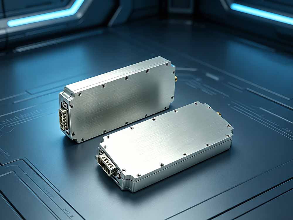
A signal source module for SDR can play several roles. It may generate a known test tone for receiver sensitivity checks. It may act as a local oscillator in a transceiver chain. It may sweep filters, calibrate gain stages, or emulate modulated signals. Each role puts different pressure on frequency accuracy, phase noise, output level, and control interfaces.
Start with the SDR workflow, not the module
Before comparing modules, define what the SDR must prove. If you test narrowband receivers, close-in phase noise matters. If you align filters, sweep speed and level flatness matter. If the module serves as an LO, locking and reference stability matter. A module that looks excellent on a datasheet may still be the wrong choice for your SDR workflow.
This is the first trap in the search for the best signal source module for SDR: treating “best” as a universal ranking. In practice, a mid-range PLL module with a clean reference can outperform a broadband module that has spurs across the band.
The specs that actually change results
Frequency range and tuning resolution
Most SDR users work from HF to 6 GHz, but covering a frequency range is not the same as performing well across it. Check harmonic filters, output amplifier compression, and tuning step size. A 1 Hz step is useful for precise offset testing. A 10 kHz step may be fine for block tuning, but it limits fine calibration work.
Phase noise and spectral purity
Phase noise is often the dividing line between a usable source and a frustrating one. For weak-signal SDR reception, close-in phase noise can mask nearby signals. For digital modes, it raises EVM and makes constellation diagrams harder to trust. Look at phase noise at 10 kHz and 100 kHz offsets, not just a single impressive number at 1 MHz.
Spurs matter too. A source with strong spurs can create false signals that look real to an SDR. Shielding, filtering, and careful board layout are not optional at higher frequencies.
Output level and level control
Calibrated output from -30 dBm to +10 dBm is practical for many SDR tests. Digital step attenuators help, but raw output level means little if flatness varies by several dB across the band. External attenuators and filters are often needed to protect the SDR front end and keep the source within a clean operating range.
Reference and stability
A TCXO is acceptable for many field tests. An OCXO or external 10 MHz reference is better for lab work, locking, and long captures. If the module cannot accept an external reference, it may limit you later. Frequency stability is especially important when you compare measurements taken hours or days apart.
Control and integration
USB is convenient, but SPI or I2C is often better for embedded SDR designs. Check API quality, Linux support, Python bindings, and whether the vendor documents register maps. A closed, GUI-only module can be painful in automated test setups. For repeatable SDR work, software control is part of the signal source.
Common module categories for SDR users
PLL/VCO source modules, such as those built around ADF4351, LMX2594, or MAX2870-class chips, are popular for CW generation, LO replacement, and sweeps. They usually need external filtering to control harmonics.
DDS modules, including AD9910-class designs, offer fast frequency agility and arbitrary waveform support. They are useful for modulation and signal emulation, but spurs can be higher, so filtering and frequency planning matter.
FPGA-based RFSoC and vector source modules provide the most flexibility, with multiple channels and wide modulation bandwidth. They also cost more and demand more engineering effort.
Matching the module to the SDR task
For receiver sensitivity tests, prioritize low phase noise, calibrated output, and good shielding. For filter or duplexer alignment, look for fast sweeps and stable output. For SDR calibration, frequency accuracy and an external reference input are key. For LO replacement, phase noise and locking behavior matter most. For signal emulation, modulation bandwidth and arbitrary waveform depth become important.
A practical selection checklist
Define frequency range and modulation needs. Set a phase noise target based on the weakest signal you must resolve. Check output level range and flatness. Confirm reference options. Verify software support. Budget for filters, shielding, attenuators, and quality cables. Finally, test the module with a known-good receiver before trusting it in a full SDR chain.
Mistakes to avoid
Do not chase the highest frequency alone. Do not ignore phase noise because the price is low. Do not assume a USB module is calibrated out of the box. Do not forget external attenuation. Do not underestimate power supply noise and shielding. These small details often decide whether a source module helps or hurts an SDR measurement.
Final thought
The best signal source module for SDR is not the one with the longest feature list. It is the one that keeps measurement uncertainty low enough for your task and integrates cleanly with your workflow. A narrowband PLL module with clean power and a stable OCXO can beat a broadband module in many SDR labs. Choose by specs, then verify with real tests.