In counter-drone RF systems, antenna gain is often treated as a headline specification. A higher dBi number sounds better, but gain does not create power. It redistributes RF energy. The real engineering question is whether that redistribution matches the mission, the frequency plan, and the legal limits.
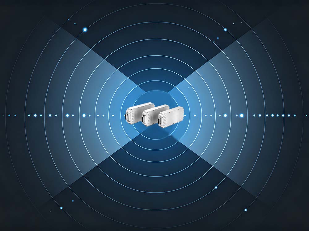
For integrators, drone jammer module antenna gain should be evaluated as part of the full RF chain, not as a standalone score.
1. Start with the Link Budget
The antenna is only one part of the system. A simplified link budget looks like this:
EIRP = P_tx + G_ant − L_feed
Where:
-
P_tx = module output power
-
G_ant = antenna gain in dBi
-
L_feed = cable, connector, filter, and protection losses
A high-gain antenna can easily lose its advantage if the feed line is long or lossy. In addition, EIRP alone does not guarantee effective jamming. The target receiver’s sensitivity, antenna, polarization, distance, and surrounding environment also matter.
2. Pattern Matters More Than Peak Gain
Two antennas with the same dBi rating can behave very differently. Beamwidth, side lobes, front-to-back ratio, and polarization purity often determine real-world performance.
| Antenna Pattern | Typical Gain Class | Beam Shape | Best Fit | Hidden Cost |
|---|---|---|---|---|
| Omnidirectional whip | Low | 360° azimuth | Close-in mobile or small perimeter | Weak long-range efficiency |
| Sector panel | Medium | 60°–120° | Fixed sector protection | Sensitive to mounting angle |
| Yagi / horn | High | 20°–60° | Long-range directional coverage | Narrow aiming tolerance |
| Phased array | High, adjustable | Electronically steered | Multi-target tracking | Cost, calibration, thermal design |
A narrow beam can concentrate energy, but it can also create blind spots. A wider beam covers more area, but may reduce range. The right choice depends on the threat direction and deployment geometry.
3. Match Gain Class to the Mission Profile
Different counter-drone missions require different antenna strategies.
| Mission Profile | Recommended Pattern | Gain Strategy | Why |
|---|---|---|---|
| Fixed perimeter sector | Sector panel | Medium gain, moderate beamwidth | Balances coverage and range |
| Long-range directional | Yagi, horn, or array | High gain, narrow beam | Concentrates energy on an approach corridor |
| Mobile or vehicle-mounted | Omni or low-gain sector | Low to medium gain | Avoids precise aiming requirements |
| Multi-target urban | Phased array or switched sectors | Adjustable gain and steering | Supports tracking and reduces blind spots |
This is why buying the highest-gain antenna available is rarely the best decision. The antenna must fit the operational profile.
4. Losses and Mismatches That Cancel Gain
Several factors can quietly reduce the benefit of a high-gain antenna:
-
Feed loss: Long coax runs and multiple connectors reduce EIRP.
-
VSWR: Poor matching reflects power and can stress the module.
-
Polarization mismatch: A linear antenna facing a circularly polarized target may lose significant energy.
-
In-band flatness: Gain may peak at one frequency but drop across the required band.
-
Mounting effects: Metal structures, radomes, and nearby objects can distort the pattern.
-
Environmental factors: Rain, dust, and temperature can affect long-term performance.
A good specification sheet should include more than a single gain value. It should show gain across the band, VSWR, beamwidth, polarization, and power handling.
5. Validate in the Lab and in the Field
Testing should not stop at a datasheet. A practical validation plan includes both controlled and real-world measurements.
| Check | Why It Matters | Lab Method | Field Check |
|---|---|---|---|
| VSWR / return loss | Protects module and confirms matching | VNA sweep | Spot check with analyzer |
| Gain pattern | Defines actual coverage | Anechoic chamber | Multiple points and heights |
| Polarization | Mismatch wastes gain | Dual-polarized probe | Rotate receive antenna |
| EIRP | Predicts link performance | Power meter + gain − loss | Received level mapping |
| In-band flatness | Keeps performance across bands | Swept measurement | Multi-band field test |
Urban and suburban environments introduce reflections, obstructions, and interference. A high-gain antenna that performs well in a chamber may behave differently near buildings, vehicles, or terrain.
6. Compliance Is Part of Antenna Selection
Drone jamming involves sensitive communication and navigation bands. Unauthorized use can interfere with legitimate wireless services, including GNSS and mobile networks. Higher antenna gain increases the potential impact area, so it also increases the need for strict compliance review.
Authorized projects should confirm:
-
Spectrum license or applicable authorization
-
Maximum permitted transmit power and EIRP
-
Allowed operating zones
-
Operator training and logging requirements
-
Shutdown procedures and fail-safe design
Technical feasibility is not the same as legal permission.
7. Procurement Questions to Ask
Before selecting a drone jammer module antenna gain specification, ask suppliers:
-
What is the in-band gain flatness?
-
What are the azimuth and elevation beamwidths?
-
What is the VSWR at maximum power?
-
What polarization does the antenna use?
-
What feed loss should be expected with the recommended cable?
-
How does the mounting bracket affect the pattern?
-
What compliance or test documentation is available?
FAQ
Does higher antenna gain always increase jamming range?
No. Range depends on EIRP, beam alignment, polarization, target receiver sensitivity, terrain, and legal power limits.
Is an omnidirectional antenna useless?
No. It is useful for close-in, mobile, or low-directionality scenarios where broad coverage matters more than long range.
How should two antennas with the same dBi be compared?
Compare beamwidth, side lobes, front-to-back ratio, polarization, VSWR, in-band flatness, power handling, and mechanical durability.
Final Takeaway
Drone jammer module antenna gain is not a standalone performance score. It is a system variable that must be balanced with beam pattern, feed losses, polarization, module power, mission profile, and legal limits.
The most reliable approach is simple: calculate the full link budget, match the antenna pattern to the mission, validate in both lab and field, and stay within authorized operating rules. That produces better counter-drone RF deployments than chasing the highest dBi number alone.