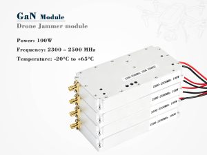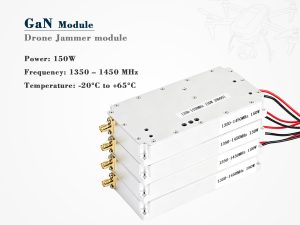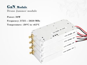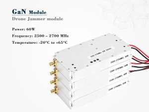
The drone jammer module interface is where RF performance, power integrity, control logic, and mechanical reality meet. In 2026, integrators are no longer asking only for raw output power. They want a module that drops into a platform with clean telemetry, predictable thermal behavior, documented pinouts, and a compliance story that survives review. This guide focuses on the interface layer — the part that decides whether a module is easy to integrate or painful to support.
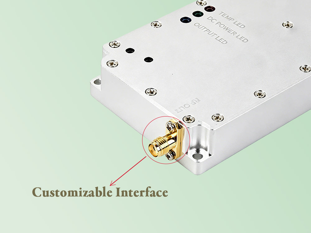
What a Drone Jammer Module Interface Actually Controls
A drone jammer module interface is not just a connector. It is a set of agreements: electrical, mechanical, thermal, protocol, and safety. A weak interface can make a strong RF module unreliable. A strong interface makes integration predictable, even when the host platform changes.
The table below shows the main interface layers that buyers should review before sampling.
| Layer | Typical Options | Why It Matters | Verification |
|---|---|---|---|
| RF | SMA, N-type, blind-mate | Impedance, VSWR, isolation, cable loss | VNA, spectrum analyzer |
| DC power | 12 V, 24 V, 28 V, 48 V | Ripple, inrush, surge, brownout behavior | Load bank, oscilloscope |
| Control | UART, CAN, RS-485, Ethernet | Command latency, telemetry, fault reporting | Protocol analyzer |
| Mechanical | Baseplate, card guide, sealed housing | Vibration, shock, service access | Shaker, IP test |
| Safety | Interlock, temperature, VSWR alarm | Fail-safe behavior and fault isolation | Fault injection |
A well-documented drone jammer module interface also defines what happens when something goes wrong. Does the module shut down? Does it report a fault? Does it limit output? These details matter more than a marketing datasheet.
Drone Jammer Module Interface Electrical and RF Requirements
RF Path and Impedance Discipline
The RF interface should state impedance, connector type, return loss, and maximum safe input from reflected power. Poor impedance matching can raise heat, reduce efficiency, and stress the final stage.
Power Integrity and Protection
DC input is often underestimated. A drone jammer module interface should document:
-
Nominal and absolute maximum voltage
-
Inrush current
-
Ripple and noise tolerance
-
Reverse polarity protection
-
Fuse or breaker recommendation
-
Grounding scheme
If the module is used in a vehicle or mobile mast, transient protection is not optional. The host system may see load dumps, inductive kickback, and brownouts. A clean interface definition prevents field failures.
Control, Telemetry, and Fail-Safe Logic
Modern modules expose temperature, forward power, reflected power, voltage, current, and fault flags. The control interface should define polling rate, command format, error codes, and recovery behavior. Without this, the host cannot distinguish a temporary warning from a critical fault.
External standards and regulatory references can help frame requirements. For example, ETSI publishes radio equipment standards, while the FCC explains why jamming devices are strictly regulated in the United States. Always confirm local law before deployment.
Drone Jammer Module Interface Protocols and Pinout Patterns
Protocol choice affects cost, latency, and system complexity. The best protocol is the one your host platform can support reliably.
| Protocol | Common Use | Strengths | Trade-offs |
|---|---|---|---|
| UART | Simple module control | Low cost, easy debug | Point-to-point, limited distance |
| CAN | Vehicle and rugged systems | Robust, multi-node | Needs termination and training |
| RS-485 | Industrial links | Long cable runs | Lower speed, polling overhead |
| Ethernet | Higher-level control | High bandwidth, remote access | More components, security needs |
| USB | Bench and service | Fast setup | Not ideal for harsh environments |
| GPIO | Safety and triggers | Deterministic | Limited data, wiring burden |
Pinout Documentation
A professional drone jammer module interface includes a pinout table with signal name, direction, voltage level, tolerance, and function. Never rely on a photo of a connector. Reverse engineering a pinout is a fast route to damaged hardware.
Connector and Cable Strategy
Use keyed connectors where possible. Label cables. Define bend radius and strain relief.
Mechanical, Thermal, and Environmental Interface Design for a Drone Jammer Module Interface
Heat is the quiet killer of RF modules. The mechanical interface must move heat from the internal die to the host chassis or heatsink.
| Design Area | Recommended Practice | Risk If Ignored |
|---|---|---|
| Mounting | Flatness, torque spec, thread locking | Loosening, poor heat transfer |
| Thermal path | Gap pad, thermal grease, baseplate | Overheating, derating |
| Sealing | Gasket, conformal coating, IP rating | Moisture and corrosion |
| Vibration | Shock mounts, cable ties, strain relief | Connector fatigue |
| Service | Access to screws, labels, diagnostics | Long maintenance downtime |
A drone jammer module interface that ignores thermal expansion can crack solder joints or degrade connectors over time.
Compliance and Safety Around the Drone Jammer Module Interface
This topic is legally sensitive. In many countries, transmitting jamming signals is illegal except for authorized government or defense use. The interface should therefore support auditability: logging, role-based control, tamper detection, and clear fault states.
Useful external references include:
-
ITU for international spectrum coordination
-
GPS.gov for GPS interference concerns
-
FCC for U.S. enforcement context
A compliant drone jammer module interface is not a loophole. It is a controlled boundary. Integrators should document authorized use, operator training, and shutdown procedures.
Testing and Validation of the Drone Jammer Module Interface
Testing should prove the interface under normal and fault conditions. Do not wait for field trials to discover a protocol bug or a thermal limit.
| Test | Goal | Tool |
|---|---|---|
| VSWR sweep | Confirm RF match | Vector network analyzer |
| Power ramp | Check inrush and stability | DC load, oscilloscope |
| Protocol stress | Validate error handling | Protocol analyzer |
| Thermal soak | Verify derating curve | Chamber, thermocouples |
| Vibration | Check connector integrity | Shaker table |
| Fault injection | Confirm fail-safe logic | Test harness |
Bench Validation
Start with a bare module, a known-good power supply, and a clear test plan. Log every command and response. A drone jammer module interface that behaves well on the bench is easier to debug later.
System Integration
Once installed, re-test with real cables, real antennas, and real host software. Cable loss, grounding, and software timing can change everything.
How to Choose a Drone Jammer Module Interface
Use this checklist when comparing suppliers:
-
Is the pinout fully documented?
-
Are voltage and current limits clear?
-
Does the protocol include fault codes?
-
Is thermal resistance specified?
-
Are connectors keyed and rated?
-
Is there an interlock or remote shutdown?
-
Does the supplier provide compliance guidance?
-
Are spare parts and cables available?
A strong drone jammer module interface reduces integration risk. A weak one shifts risk to your team.
FAQ
What is a drone jammer module interface?
It is the combined electrical, RF, mechanical, thermal, and protocol boundary between a jammer module and its host platform.
Which connector is best for a drone jammer module interface?
It depends on frequency, power, vibration, and service needs. SMA is common for lower power, while N-type or blind-mate solutions may suit rugged systems.
How do I reduce EMI at the interface?
Use shielded cables, proper grounding, filtered power, and short return paths. Document the shielding strategy in the interface control drawing.
Can I integrate any module into any platform?
No. The drone jammer module interface must match power, thermal, protocol, and legal requirements. Always validate with authorized engineering and compliance teams.
Final Take
The drone jammer module interface is a systems problem, not a connector problem. In 2026, the best modules will win on documentation, telemetry, thermal design, and compliance support. Buyers who treat the interface as an afterthought will pay for it in integration time, field failures, and regulatory risk.