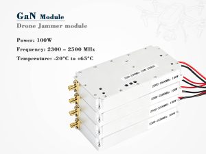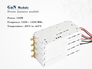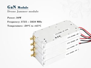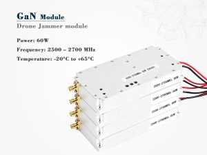
The phrase “how to build a drone jammer module” sounds like a DIY electronics project. In reality, it describes a regulated RF engineering problem. A module that radiates jamming signals can interfere with licensed spectrum, public safety communications, GNSS, and aviation. That is why this article treats “build” as a system-engineering and compliance exercise—not a wiring guide. It does not include schematics, bills of materials, power levels, or tuning steps. Instead, it maps the layers a professional team must understand before any authorized prototype leaves the bench.
Start with the legal boundary, not the circuit
In many countries, transmitting jamming signals is illegal except for government or authorized defense users. Building or owning such equipment may also be restricted. Testing is usually limited to shielded rooms, conducted setups, or licensed facilities. If the real goal is counter-UAS capability, detection, tracking, identification, and non-jamming mitigation should come first.
| Region | General stance | Practical takeaway |
|---|---|---|
| United States | FCC prohibits unauthorized jamming; limited federal exceptions | Commercial development needs legal counsel and authorized test spectrum |
| European Union | National regulators enforce; jamming is generally prohibited | CE marking does not authorize transmission |
| United Kingdom | Ofcom regulates spectrum; jamming equipment use is illegal | Focus on detection or authorized C-UAS programs |
| Other regions | Rules vary widely | Verify local law before any design work begins |
This is not legal advice. Any real project needs a qualified spectrum lawyer and regulator engagement.
The module as a system, not a single board
A drone jammer module is often imagined as one PCB. In practice, it is a stack of subsystems. Each layer raises different engineering and compliance questions.
| Layer | What it does | Compliance or engineering note |
|---|---|---|
| RF front end | Filters, amplifiers, antennas | Must control out-of-band emissions; shielded testing is essential |
| Signal generation | SDR, FPGA, or dedicated waveform source | Waveform control and spectrum shaping matter more than raw power |
| Control plane | Timing, failsafes, logging | Prevents unintended transmission and supports audits |
| Power and thermal | Batteries, heatsinks, duty cycle | Reliability and safety depend on thermal design |
| Mechanical and EMC | Enclosure, shielding, grounding | Must meet EMC and safety expectations without compromising cooling |
RF chain design questions that matter
Several high-level questions shape the RF chain:
-
Spectrum: Which bands are involved? Common drone links use 2.4 GHz and 5.8 GHz, while GNSS is also a sensitive topic. Targeting these bands raises serious safety and legal issues.
-
Bandwidth: A wider signal is not automatically better. Occupied spectrum affects interference risk and regulatory exposure.
-
Filtering: Harmonic and spurious emissions must be suppressed. Poor filtering can disrupt nearby systems.
-
Antenna behavior: Directional and omnidirectional designs create very different coverage and interference profiles.
-
Receiver protection: If the module includes sensing, its own transmission can damage sensitive receive components without proper isolation.
Thermal and power realities
Thermal design is often underestimated. RF power amplifiers generate concentrated heat, and batteries must supply high current safely.
| Subsystem | Typical challenge | Design response |
|---|---|---|
| RF power amplifier | Heat density | Heatsink, fan, thermal pad, derating |
| Battery pack | High current draw | BMS, fusing, safe chemistry |
| Duty cycle | Continuous operation | Thermal cutoff and defined duty limits |
| Enclosure | IP rating vs. cooling | Balance vents, filters, and EMI shielding |
Control, safety, and logging
A professional module needs more than RF output. It needs controlled behavior.
Key elements include hardware interlocks, software watchdogs, emergency stop logic, firmware signing, and audit logs. These features reduce the chance of accidental transmission and help prove responsible operation during authorized testing.
Testing without causing interference
Testing should never begin with open-air transmission. A responsible sequence is:
-
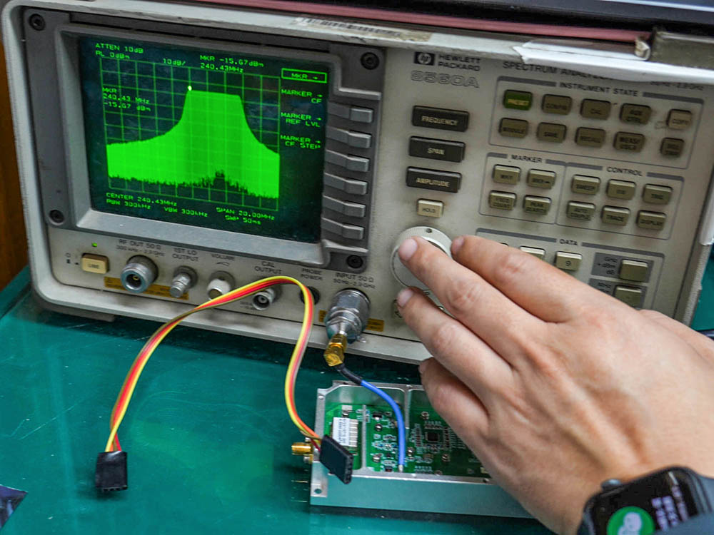
Conducted tests with attenuators and a spectrum analyzer.
-
Shielded room or anechoic chamber validation.
-
Authorized open-air testing only with spectrum coordination.
-
Emissions mask, spurious, thermal, and battery verification.
-
Full documentation for legal and engineering review.
Common mistakes
-
Treating a jammer as a cheap DIY gadget.
-
Ignoring legal review until after prototyping.
-
Underestimating thermal and battery constraints.
-
Assuming higher power equals better performance.
-
Skipping filters and spectrum shaping.
-
Building without fail-safe or logging features.
Conclusion
The real answer to “how to build a drone jammer module” is to build a compliance-first RF program. Start with legal review, then system architecture, controlled testing, and safety. If the objective is counter-drone capability, begin with detect-and-decide layers and work with authorized partners. The technology is complex, but the legal and ethical boundaries are even more important.