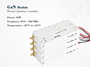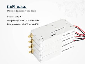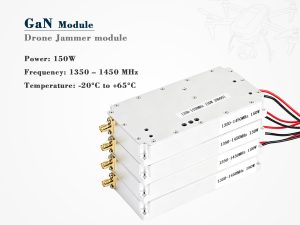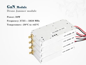
Integrating a drone jammer module is not simply a matter of mounting an RF device inside a counter-UAS platform. It is a systems engineering task that touches power, thermal behavior, RF coexistence, control logic, environmental hardening, and legal compliance. A module that performs well on a bench may fail in the field if these areas are treated as secondary concerns.
This guide is intended for engineers, program managers, and procurement teams working on authorized counter-UAS programs. It focuses on integration principles and does not provide instructions for building, tuning, or operating jamming equipment.
What Integration Really Means
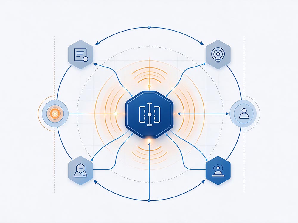
In a counter-drone system, the jammer module must behave as one reliable subsystem among many. It must connect cleanly to the platform, communicate with the command-and-control layer, survive vibration and temperature swings, and avoid disrupting other RF systems on the same platform.
Poor integration often shows up as overheating, unexpected interference, false alarms, shortened battery life, or certification delays. Good integration begins with clear requirements: the authorized use case, platform constraints, environmental profile, and applicable regulations.
Core Integration Layers at a Glance
| Layer | What to define | Why it matters |
|---|---|---|
| Mechanical | Dimensions, mounting, connectors, IP rating, vibration profile | Ensures fit, durability, and serviceability |
| Power | Voltage range, inrush current, protection, grounding | Prevents resets, damage, and unstable output |
| Thermal | Heat load, duty cycle, airflow, conduction paths | Avoids derating, shutdowns, and component stress |
| RF | Antenna ports, filtering, isolation, coexistence | Protects spectral integrity and reduces interference |
| Control | Interfaces, protocols, telemetry, fail-safe logic | Enables reliable command and safe behavior |
| EMI/EMC | Shielding, bonding, cable routing, filtering | Supports certification and platform compatibility |
| Compliance | Authorization, logging, access control, limits | Keeps deployment lawful and auditable |
Engineering Priorities That Decide Success
Power and transient behavior
Jammer modules can draw significant current in short bursts. Integration should account for supply sag, inrush current, fuse selection, reverse-polarity protection, and clean grounding. If the module shares power with sensitive avionics or radios, isolation and filtering become critical.
Thermal design and duty cycle
Thermal performance is often the limiting factor. The integration team should model heat generation under realistic duty cycles, not just peak output. Conduction cooling, forced air, heat sinks, and thermal interface materials must be selected together. In enclosed platforms, derating may be necessary.
RF coexistence and antenna planning
A jammer module rarely operates alone. GPS receivers, communication radios, radar, and telemetry links may all be nearby. Antenna placement, cable shielding, filtering, and physical separation help reduce self-interference. The goal is not only effective counter-UAS performance but also preserving the platform’s other RF functions.
Control, telemetry, and fail-safe logic
The drone jammer module should expose clear control interfaces and status telemetry. Operators need to know whether it is ready, active, faulted, or inhibited. Fail-safe behavior matters: if communication is lost or authorization expires, the system should return to a safe state. Role-based access and audit logging also support responsible use.
EMI/EMC and environmental hardening
Electromagnetic compatibility is not a final checkbox. It should be designed in from the start through grounding strategy, shielded enclosures, filtered feedthroughs, and cable routing. Environmental testing should cover temperature, humidity, vibration, shock, and ingress protection as required by the deployment scenario.
A Practical Integration Workflow
-
Define the authorized use case. Confirm legal basis, operating conditions, and performance envelope.
-
Model interfaces early. Document mechanical, electrical, thermal, RF, and software boundaries.
-
Bench-test the module. Verify power, control, telemetry, and thermal behavior before platform installation.
-
Integrate with the platform. Address grounding, cable routing, antenna placement, and structural mounting.
-
Validate in realistic conditions. Test vibration, temperature, EMI, and RF coexistence.
-
Document and train. Provide installation records, operating limits, maintenance procedures, and user training.
Testing and Validation Checklist
-
Power quality under peak and idle loads
-
Thermal rise at expected duty cycles
-
Vibration and shock resilience
-
RF isolation and coexistence with platform radios
-
Control latency, telemetry accuracy, and fail-safe response
-
EMI/EMC pre-compliance and formal testing
-
Environmental sealing and corrosion resistance
-
Cybersecurity access controls and log integrity
Legal and Operational Compliance
Jamming transmitters are heavily regulated in most countries. In many jurisdictions, only authorized government or defense users may operate them. Integration should therefore include technical and procedural safeguards: authorization interlocks, geofencing where appropriate, audit trails, role-based permissions, and clear operating limits.
Procurement teams should request documentation covering RF exposure, EMC, environmental qualifications, cybersecurity, and maintenance requirements. Compliance should be reviewed early, because late changes can be expensive and may delay deployment.
Common Integration Mistakes
-
Treating the jammer module as a standalone product rather than a subsystem
-
Ignoring thermal derating until field trials
-
Routing RF and digital cables without separation or shielding
-
Delaying compliance review until the end of the program
-
Omitting fail-safe behavior and operator feedback
-
Underestimating power transients and grounding issues
Final Thoughts
Successful drone jammer module integration is a discipline of interfaces. The module must fit, receive clean power, stay cool, coexist with other RF systems, respond to control commands, and satisfy legal requirements. When these elements are addressed early, the result is a more reliable counter-UAS capability with fewer surprises in testing and deployment.
For teams working on C-UAS platforms, the best approach is simple: treat integration as a first-class engineering program, not an afterthought.