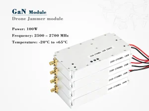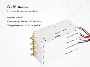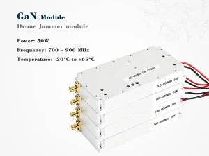
A jammer module can pass RF bench tests and still fail in the field when its thermal path was treated as an afterthought. Effective drone jammer module heat dissipation is a budget problem: every watt dissipated by the GaN stages must travel from the die to the package, through a thermal interface, into a spreader or cold plate, and finally into air or liquid. If any stage is undersized, junction temperature rises, and RF performance starts to move.
This checklist is written for counter-UAS hardware teams that need repeatable thermal decisions rather than a single heatsink recommendation.
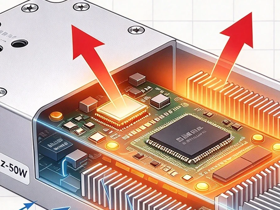
1. Start with a worst-case thermal budget, not a nominal wattage
Use the highest ambient temperature, the longest transmit duty cycle, and the worst allowable airflow or coolant inlet temperature. Add margin for adjacent modules and enclosure heat soak. A module rated at 100 W RF is not automatically a 100 W heat load; efficiency, combining losses, and control electronics all contribute. Document the budget in a simple line-item table so mechanical, RF, and systems engineers review the same numbers.
2. Treat the thermal interface as a controlled joint
Thermal interface material (TIM) is not a gap filler chosen at the end of the build. Thickness, mounting pressure, flatness, and voiding matter. Too much TIM adds resistance; too little can leave air gaps. For fielded modules, also consider pump-out and dry-out under repeated thermal cycling. Use a mounting pattern that keeps pressure even across the GaN footprint, and verify it with a thermal camera or junction-temperature measurement, not only by torque specification.
The mechanical interface deserves the same attention. Connector placement, gasket compression, and mounting bosses can either spread heat into the enclosure or create a bottleneck. Before finalizing the thermal stack, review the drone jammer module interface because enclosure and connector decisions often limit how much heat can actually leave the module.
3. Match the cooling architecture to the deployment profile
Air cooling is simpler and more serviceable, but it depends on inlet clearance, filter maintenance, and fan reliability. Liquid cold plates handle higher heat flux and tighter enclosures, but they add fittings, coolant compatibility, and leak-risk requirements. The right choice depends on duty cycle and installation, not on a generic preference.
| Thermal path stage | What to verify | Common weak point |
|---|---|---|
| GaN die to package | Junction temperature margin at maximum duty cycle and worst ambient | Using datasheet junction-to-case resistance as if it were a complete system value |
| Package to spreader | TIM thickness, pressure, voiding, and pump-out resistance | Uneven mounting or excessive compound thickness |
| Spreader to cold plate or heatsink | Heat spreading, surface flatness, and contact area | Hot spots under small GaN footprints |
| Cold plate or air path | Flow rate, pressure drop, fouling, and fan-failure behavior | Sizing for nominal conditions instead of peak load |
| Enclosure to ambient | Inlet and outlet clearance, recirculation, and sealing | IP-rated sealing that blocks the intended airflow path |
4. Validate at the module level and the system level
A cold-plate test with a laboratory chiller can hide a weak design. Validate the module inside its enclosure, with the real fan curve or coolant loop, at the real inlet temperature. Run warm-up, steady-state, and cycling tests. Measure case, cold-plate, and ambient temperatures together so the team can see where the thermal resistance actually sits. If the module uses telemetry, log junction or board temperatures during RF pulsing; thermal faults often appear as short excursions before a shutdown.
5. Design for maintenance and degradation
Dust, filter loading, coolant fouling, and fan aging all reduce heat dissipation over time. Specify service intervals and alarm thresholds based on measured degradation, not only on first-article performance. For air-cooled units, confirm that filters can be replaced without disturbing RF connections. For liquid-cooled units, define coolant quality, fill procedure, and leak inspection points.
Conclusion
Drone jammer module heat dissipation is most reliable when it is designed as a chain of controlled resistances from junction to ambient. Start with a worst-case budget, qualify the TIM joint, choose cooling architecture for the deployment, and validate the complete enclosure. Teams that treat thermal design as a late mechanical add-on usually discover the problem in the field; teams that treat it as a system requirement catch it on the bench.