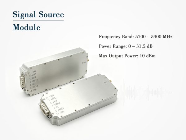
Compact 3.4–3.6GHz Signal Source Module with RS485
10dBm signal source module covering 3400–3600MHz, 0–31.5dB attenuation, RS485 control, DC12–29V, SMA female output. 146x63x17.5mm, 0.21kg. Reliable for test & integration.
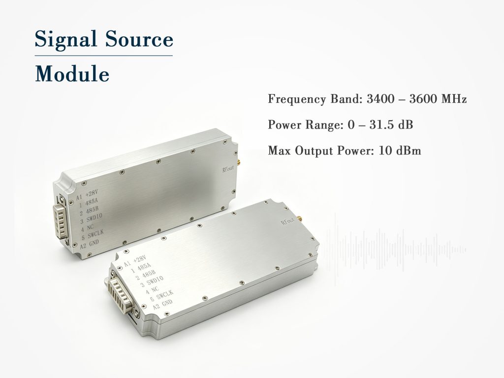
Technical Specifications
| Parameter | Typical Value |
| Signal type | Digital signal source |
| Operating band | 3400 – 3600 MHz |
| Max output power | 10 dBm |
| Output VSWR | ≤ 2.0 |
| Supply voltage | DC 12 – 29 V |
| Max current | 200 mA @ 28V |
| Attenuation range | 0 – 31.5 dB |
| Attenuation step | 0.5 dB |
| RF connector | SMA female |
| Power/control connector | 7W2 |
| Control interface | RS485 |
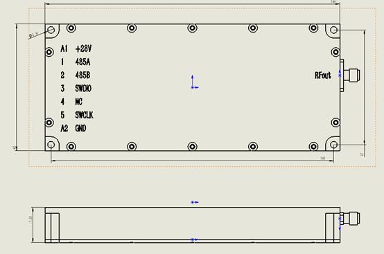
| Dimensions (L×W×H) | 146 × 63 × 17.5 mm |
| Weight | 0.21 kg |
Product Details
A Practical Signal Source Module for 3.5GHz Band Applications
When you are piecing together an RF test bench or embedding a stable local oscillator into a larger system, the last thing you want is a bulky, power-hungry box that complicates your cabling and control logic. This Signal Source Module has been designed with exactly those frustrations in mind. It delivers a clean digital-type signal across the 3400–3600MHz range, with a modest 10dBm maximum output that plays nicely with mixers, upconverters, and receiver front‑ends.
What makes this unit stand out is its straightforward RS485 interface. You are not forced into proprietary software or quirky USB‑to‑UART dongles – just standard differential commands for frequency selection and output level adjustment. The built‑in attenuator gives you 0 to 31.5dB of range in 0.5dB steps, so you can dial back the power precisely when testing sensitivity or evaluating gain compression.
Power and Physical Integration
The signal source module accepts a wide DC input from 12V all the way up to 29V, drawing only 200mA at 28V. That means you can run it off a common 24V industrial supply or a 12V battery pack without worrying about regulators overheating. The 7W2 combo connector handles both power and supply control in one physical port – a thoughtful touch for rack‑mount setups where every rear‑panel slot counts.
Dimensionally, it is quite lean: 146mm long, 63mm wide, and just 17.5mm thick. At 0.21kg, it adds negligible weight to a portable test kit. The SMA female output is robust and compatible with standard semi‑rigid or flexible cables, and the output VSWR stays ≤2.0 across the entire band, ensuring minimal mismatch loss when cascading with other components.
Who Benefits from This Signal Source Module?
Field engineers who perform drive‑testing in the 3.5GHz CBRS or 5G NR bands will appreciate the quick settling time and repeatable step attenuation. Lab technicians can use it as a reference source for receiver calibration, because the output level is predictable and the RS485 polling allows for automated sweeping. System integrators often pair two or three of these modules to create phase‑coherent multi‑channel setups – the compact footprint makes that feasible even in 1U chassis.
We have also paid attention to thermal performance. The metal housing acts as a heat spreader, so even at maximum output and elevated ambient temperatures, the frequency stability remains within acceptable bounds for most production tests. No fan, no acoustic noise – just a solid block that does its job.
Control and Configuration Made Simple
RS485 operation uses a half‑duplex two‑wire bus with a standard baud rate (default 9600, but configurable). The command set is minimal: set attenuation, read back current setting, and enable/disable the RF output. There is no complicated register map – you can have it running within five minutes of power‑up. For systems that already have a PLC or microcontroller with UART, integration is almost plug‑and‑play.
The 0.5dB step size is fine enough for most gain‑setting tasks, while the 31.5dB total range covers everything from near‑full output to a very quiet signal that won’t overload a low‑noise amplifier. And because the output is internally terminated, you do not need external pads for basic matching.
Frequently Asked Questions
Case Studies
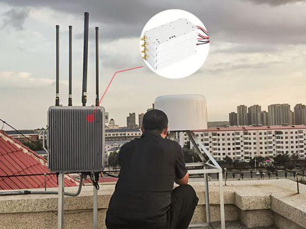
Heilongjiang Weather Center Completes Anti-Drone System Upgrade with Three High-Power Drone Jammer Modules

Tangshan Chem Plant Sealed Drone Gaps With 3 GaN Wideband Modules

How a National Prison Integrated Our Drone Jamming Module Into Their Fixed Counter-Drone System

Integrating Core RF Power: OEM Drone Jamming Module for Oil Refinery Security | Case Study
Send Us a Message
Related Products
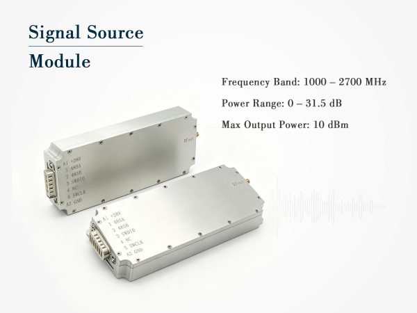
Wideband Signal Source Module – 1000 to 2700MHz, 10dBm with Digital Attenuator
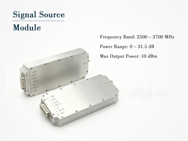
Compact Signal Source Module – 2500–2700MHz, 10dBm with Digital Attenuation
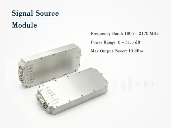
Digital Signal Source Module 1805-2170MHz