A drone jammer module pinout is often treated as a simple connector map. In practice, it is a contract between the module, the host platform, and the integrator. A pinout document tells you what each interface is expected to do, how power and control signals are separated, and which signals must never be mixed. For 2026 integration teams, the real challenge is not finding a connector—it is verifying that the pinout matches the module revision, the harness, and the intended authorized use case.
This guide takes a documentation-first approach. It does not provide a universal wiring diagram, because jammer modules vary widely by manufacturer, frequency band, output architecture, and regulatory market. Always use the manufacturer’s datasheet and written approval for the exact module revision.
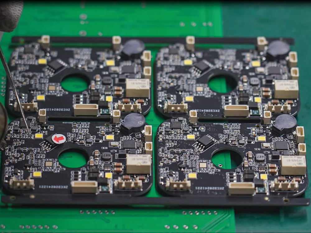
Why the pinout is more than a connector table
A mature pinout review covers six areas: DC power, control and telemetry, RF output, enable/interlock logic, grounding and shielding, and mechanical keying. Teams that review only the connector shape often miss revision changes, inverted logic levels, or isolated-ground requirements.
The safest assumption is simple: a pinout is revision-specific. A harness that worked with an early sample may not be valid for a production batch. Ask for the pinout by part number, hardware revision, and firmware version where relevant.
Six interface blocks to verify
| Interface area | What to verify in the datasheet | Common integration mistake |
|---|---|---|
| DC power input | Voltage range, peak current, inrush behavior, fuse recommendation, reverse-polarity protection | Assuming a nominal voltage is the same as the absolute maximum |
| Control and telemetry | Logic level, protocol, isolation, baud rate, command set, error reporting | Connecting a 3.3 V control line to a 5 V host without level shifting |
| RF output | Connector type, impedance, frequency band, maximum output, load protection | Treating an RF coaxial port as a low-voltage logic pin |
| Enable/interlock | Active-high or active-low logic, debounce, hardware kill path, fault behavior | Leaving enable floating or bypassing the interlock during bench tests |
| Grounding and shielding | Chassis ground, signal ground, shield termination, isolation boundaries | Creating ground loops through the harness and enclosure |
| Mechanical keying | Connector family, mating cycles, strain relief, keying orientation, environmental sealing | Forcing a similar-looking connector into the wrong keyed housing |
For a deeper look at connector and control-interface trade-offs, see our companion article: 5 Drone Jammer Module Interface Secrets for 2026.
What 2026 pinout reviews should include
In 2026, counter-drone hardware teams are under more pressure to document interface decisions. Procurement teams want traceability. Test teams want repeatable fixtures. Compliance teams want evidence that the module is used only in authorized environments. A pinout review should therefore produce more than a harness drawing.
A practical review package includes:
-
A controlled pinout table tied to the module part number and revision.
-
A harness drawing with connector orientation and wire gauge.
-
A power budget with inrush and thermal notes.
-
A control-interface map showing protocol, logic levels, and isolation.
-
A test plan for continuity, polarity, and safe enable behavior.
-
A change log that records pinout revisions and approvals.
A documentation-first workflow
Start with the manufacturer’s pinout and compare it against the physical labels on the module. Do not rely on wire colors alone. Next, verify that the host platform’s I/O voltage and ground references match the module requirements. Then review the RF section separately, because RF ports follow different safety and impedance rules from DC and logic interfaces.
Before powering a production harness, use a current-limited bench supply and a documented test fixture. Confirm enable and interlock behavior with the RF output disabled. Record the results by serial number. This may feel slow, but it prevents the most expensive failure mode: a harness that works once and fails intermittently in the field.
Compliance and authorized use
Drone jammer modules are regulated products in many jurisdictions. Pinout documentation should not be confused with authorization to operate. Integrators should confirm that the module, host platform, and test environment comply with local radio, safety, and spectrum rules. The pinout is an engineering document; it is not a license to transmit.
FAQ
Is a drone jammer module pinout universal?
No. Pinouts vary by manufacturer, model, revision, and sometimes firmware configuration.
Can I use wire colors as the pinout?
Only as a secondary check. Use the manufacturer’s written pinout and verify continuity with a meter.
Should RF output pins be treated like logic pins?
No. RF ports are coaxial interfaces with impedance and load requirements; they are not DC logic headers.
What is the most important pinout check?
Power polarity and control-logic compatibility, followed by enable/interlock behavior with RF output disabled.
A reliable drone jammer module pinout review is a documentation discipline, not a guessing game. In 2026, the teams that succeed will be those that treat every pin, revision, and approval as part of the same controlled interface package.