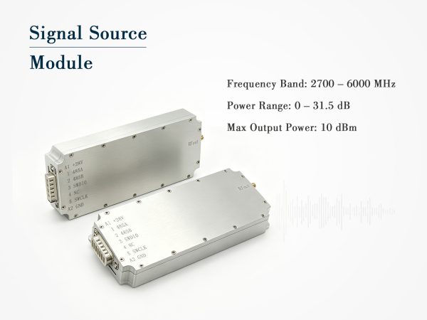
Digital Signal Source Module – 5700–5900MHz, 10dBm
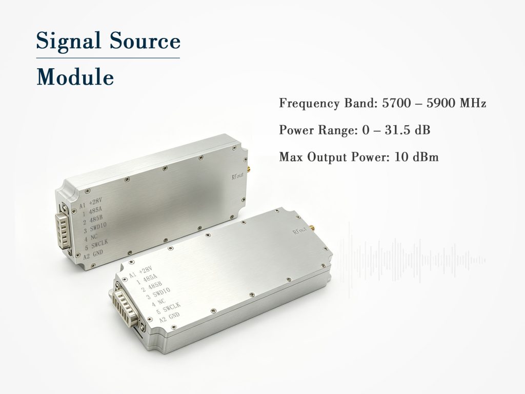
5700–5900MHz digital signal source module, 10dBm output, 0–31.5dB attenuation, RS485 control, SMA female, 12–29V DC. Compact 146*63*17.5mm, 0.21kg.
Practical Use Cases
Production testing of 5.8GHz Wi-Fi or ISM-band transceivers – use the digital signal source module as a golden reference.
Radar target simulation – modulate the output with external pulse generators via the RS485 command set.
Educational labs – demonstrate power leveling and impedance matching without bulky bench equipment.
Technical Specifications
| Parameter | Typical Value |
| Signal type | Digital signal source |
| Operating frequency band | 5700~5900MHz |
| Maximum output power | 10dBm |
| Output VSWR | ≤2.0 |
| Operating voltage | DC12V~29V |
| Max operating current | 200mA @28V |
| Attenuation range | 0~31.5dB |
| Attenuation step | 0.5dB |
| Output connector | SMA female |
| Power/control connector | 7W2 |
| Control interface | RS485 |
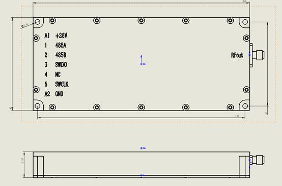
| Dimensions (LWH) | 146*63*17.5mm |
| Weight | 0.21kg |
Product Details
Digital Signal Source Module: Precision RF Generation for 5.8GHz Applications
When your test bench or embedded system demands a stable, digitally controlled RF carrier, the digital signal source module presented here delivers exactly that. Engineered for the 5700–5900MHz band, this compact unit combines a clean digital signal source with a built-in step attenuator, making it a versatile building block for radar simulation, wireless equipment verification, and frequency-agile systems.
Core RF Performance at a Glance
The module outputs a maximum power of +10dBm into a 50Ω load, with output VSWR kept at or below 2.0 across the entire operating band. This ensures minimal mismatch loss and consistent signal integrity when connecting to antennas, filters, or downconverters. The digital signal source module uses a direct digital synthesis architecture, which provides fast frequency settling and low phase noise – critical for coherent measurement scenarios.
Power adjustment is where this unit truly shines. You get a 0 to 31.5dB attenuation range with 0.5dB step resolution, allowing fine-grained level control without external pads. Whether you are sweeping receiver sensitivity or calibrating a spectrum analyzer front-end, this integrated attenuation saves board space and reduces insertion loss from external cables.
Power Supply and Interface Flexibility
Wide input voltage tolerance (DC 12V to 29V) makes the digital signal source module compatible with both fixed laboratory supplies and mobile battery packs. Maximum current consumption is only 200mA at 28V, so thermal management remains straightforward even in enclosed housings. The 7W2 hybrid connector carries both DC power and supply control signals, while a separate RS485 interface handles all digital commands. This two-wire bus supports daisy-chaining multiple modules in a multi-channel system – ideal for phased-array testing or MIMO front-end characterization.
Mechanical Footprint for System Integration
Measuring just 146×63×17.5mm and weighing 210 grams, the module fits into standard 1U rack trays or portable instrument enclosures. The SMA female output connector is rugged and widely compatible with semi-rigid cables and attenuator pads. All mounting holes are placed on a 0.1-inch grid, simplifying mechanical design in custom chassis.
Practical Use Cases
-
Production testing of 5.8GHz Wi-Fi or ISM-band transceivers – use the digital signal source module as a golden reference.
-
Radar target simulation – modulate the output with external pulse generators via the RS485 command set.
-
Educational labs – demonstrate power leveling and impedance matching without bulky bench equipment.
Why Choose This Digital Signal Source Module?
Compared to general-purpose signal generators, this module offers deterministic latency, deterministic step sizes, and a command protocol that returns status bytes in under 1ms. The absence of mechanical potentiometers improves long-term reliability, and the sealed metal housing provides both EMI shielding and mechanical protection. For OEM integrators, the RS485 command set is fully documented with broadcast and addressed modes, enabling synchronous phase adjustments across multiple units.
Frequently Asked Questions
Case Studies
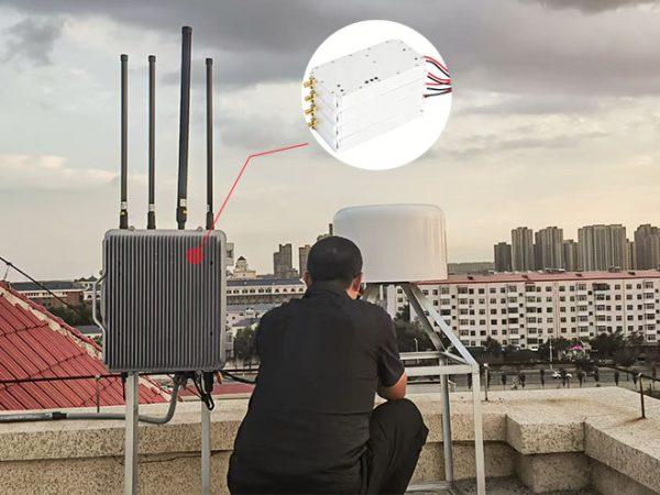
Heilongjiang Weather Center Completes Anti-Drone System Upgrade with Three High-Power Drone Jammer Modules

Tangshan Chem Plant Sealed Drone Gaps With 3 GaN Wideband Modules

How a National Prison Integrated Our Drone Jamming Module Into Their Fixed Counter-Drone System

Integrating Core RF Power: OEM Drone Jamming Module for Oil Refinery Security | Case Study
Send Us a Message
Related Products
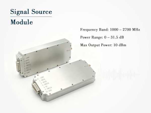
Wideband Signal Source Module – 1000 to 2700MHz, 10dBm with Digital Attenuator
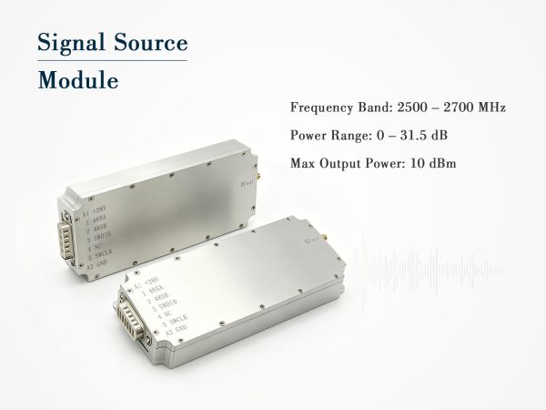
Compact Signal Source Module – 2500–2700MHz, 10dBm with Digital Attenuation
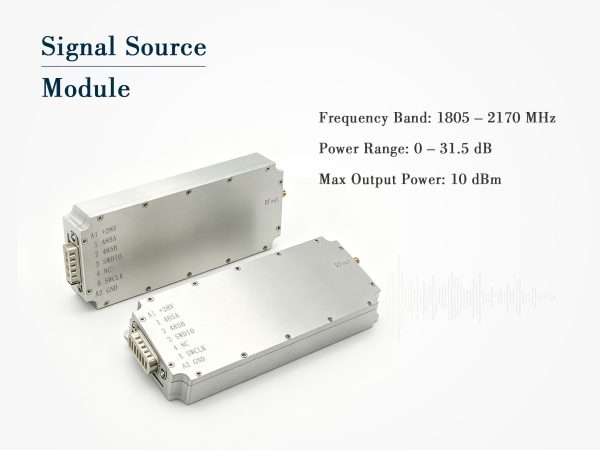
Digital Signal Source Module 1805-2170MHz