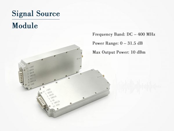
400-500MHz Signal Source Module with 0.5dB Step & RS485
400-500MHz digital signal source module with RS485, 10dBm max, 0.5dB step, SMA female, compact.

Technical Specifications
| Parameter | Typical Value |
| Frequency Range | 400 – 500 MHz |
| Signal Type | Digital signal source |
| Max Output Power | +10 dBm |
| Output VSWR | ≤ 2.0 |
| Power Adjustment Range | 0 – 31.5 dB (0.5 dB step) |
| Control Interface | RS485 |
| Supply Voltage | 12 V – 29 V DC |
| Max Current | 200 mA @ 28 V |
| Output Connector | SMA female |
| Power/Control Connector | 7W2 |
| Dimensions | 146 × 63 × 17.5 mm |
| Weight | 0.21 kg |
Product Details
Testing in the 400–500 MHz band comes with its own set of challenges. You need a source that is stable, easy to integrate, and offers fine enough level control to catch subtle non-linearities. This digital signal source module was built with exactly that in mind.

Covering 400–500 MHz, the module outputs a clean continuous wave up to +10 dBm. What makes it particularly handy is the 31.5 dB attenuation range adjustable in 0.5 dB increments — not the usual 1 dB coarse steps. Paired with RS485 connectivity and a compact 7W2 connector that handles both power and data, it slots into automated test racks without adding clutter.
Why Half-dB Steps Make a Difference
When you’re characterizing an LNA or a receiver front-end, jumping by 1 dB can skip right over the compression knee. With 0.5 dB resolution, you can map the gain curve more accurately. In automated test sequences, those smaller steps translate to more reliable pass/fail limits. And because the attenuation is digitally controlled, you get repeatable results every time you run the script — no mechanical attenuator drift to worry about.
Simple Integration Through RS485 and 7W2
Forget USB-to-serial dongles and extra power bricks. The 7W2 mixed D-sub connector brings RS485 data and DC power into one tidy interface. Supply anything from 12 V to 29 V DC; at 28 V, the module draws a mere 200 mA. If you’re setting up a multi-channel test system, you can daisy-chain multiple modules on a single RS485 bus. Address them individually and you’ve got a scalable, synchronized signal farm.
Compact Enough to Go Anywhere
At 146 × 63 × 17.5 mm and only 0.21 kg, the module is smaller than most bench signal generators. You can mount it directly inside a shielded enclosure, attach it to a test jig, or carry it between stations. The SMA female output keeps connections straightforward with standard RF cables. A VSWR of ≤2.0 means the output remains well-behaved even if the load isn’t perfect, which is a lifesaver when working with antennas or unmatched filters.
Reliable Performance in Every Sweep
Because the signal is synthesized digitally, frequency drift and phase noise are kept low. This is crucial when you are running long-duration tests or when multiple modules must stay coherent. The wide supply range (12–29 V) means you can pull power from a vehicle battery, a PLC rail, or a standard lab supply, and the module will happily start up every time.
Where You’ll Use This Signal Source Module
-
ISM and LPWAN device testing: Hit the exact frequencies for LoRa (433 MHz), Sigfox, and other sub-GHz protocols.
-
Amateur radio equipment: Useful for 70 cm band receiver sensitivity checks.
-
RF component validation: Sweep filters, attenuators, and amplifiers with precise power levels.
-
Production line checks: Embed the module into a test fixture and automate calibration via RS485.
-
Educational labs: Students can learn about UHF signal behavior without the cost of a full-size signal generator.
Ready to Put It to Work
Whether you need a dedicated CW source for your RF bench or a building block for a larger ATE system, this 400–500 MHz signal source module balances precision, ease of control, and portability. Hook it up, send a few ASCII commands over RS485, and you’ve got a clean, calibrated signal right where you need it.
Frequently Asked Questions
Case Studies

Drone Jammer Module Integration for Tianjin Binhai Military C-UAS

Tangshan Chem Plant Sealed Drone Gaps With 3 GaN Wideband Modules
How a Military Unit in Xi’an Upgraded Its Entire Anti-Drone Fleet With Our OEM Jamming Modules

How a National Prison Integrated Our Drone Jamming Module Into Their Fixed Counter-Drone System
Send Us a Message
Related Products

4800-5000MHz Signal Source Module | 0.5dB Step RS485

2300-2500MHz Signal Source Module with RS485 & 0.5dB Step

1800-2000MHz Signal Source Module with RS485 & 0.5dB Step