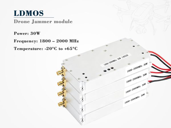
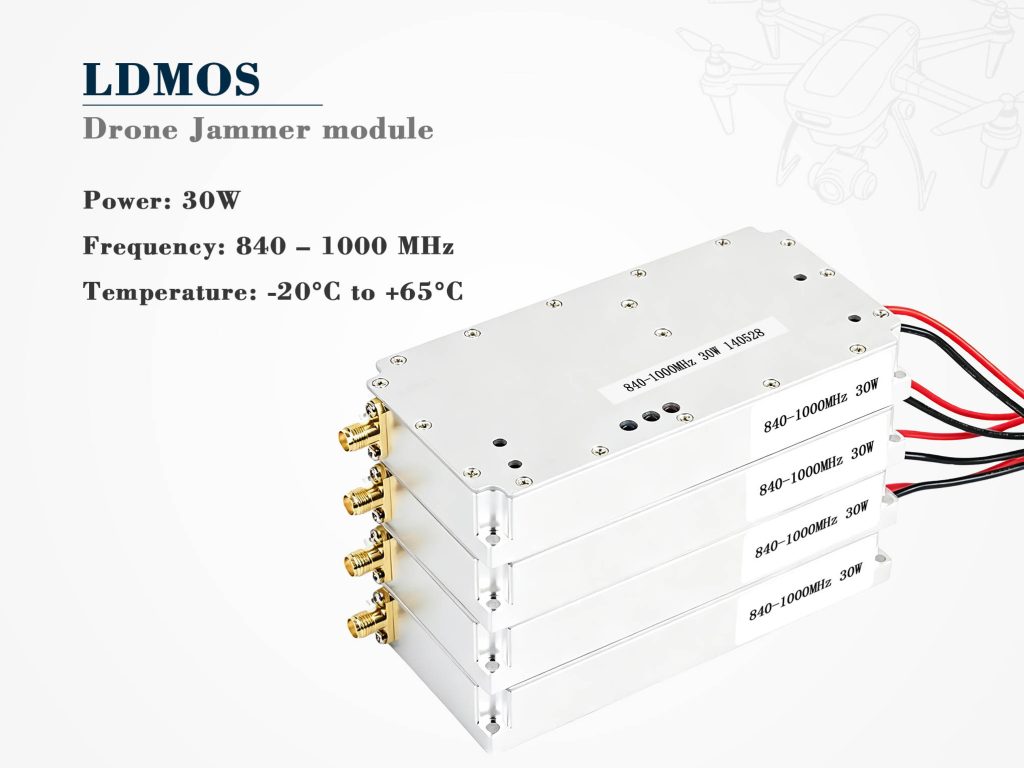
30W Anti UAV Module 840-1000MHz LDMOS Analog Jammer
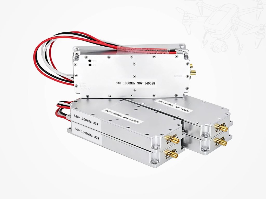
30W anti UAV module covering 840–1000MHz with built-in analog sweep source, 24–29V DC, 3.2A max, SMA female, 115.5×46.5×21mm, 0.21kg.
Technical Specifications
| Parameter | Specification | Notes |
| Frequency range | 840–1000 MHz | Covers common drone control and video links |
| Output power | 30 W nominal | LDMOS final stage, efficiency ≥40% |
| Supply voltage | DC 24–29 V | Regulated supply recommended |
| Current draw | 3.2 A max | Allow surge headroom for cold start |
| Modulation source | Built-in high-speed analog sweep | No external source required |
| Analog scan speed | High-speed continuous sweep | Factory-set full-band analog sweep |
| Input / output impedance | 50 Ω | SMA female output, VSWR ≤2.0 |
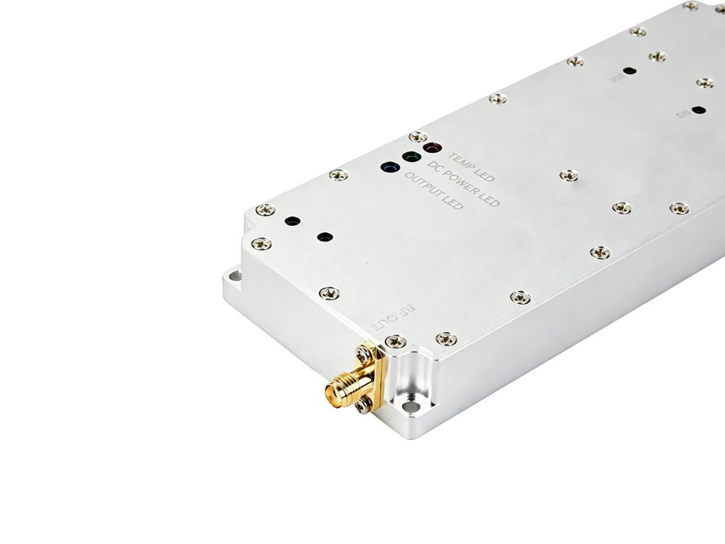
| Protection LEDs | Power, overvoltage, overtemperature | Status visible on module |
| Operating temperature | -20 to +65 °C | Baseplate cooling recommended |
| Dimensions (L×W×H) | 115.5 × 46.5 × 21 mm | Compact module |
| Weight | 0.21 kg | Aluminum housing |
| Base material | Aluminum alloy housing / high-frequency PCB | For thermal and RF performance |
Product Details
The 30W anti UAV module is a compact LDMOS analog interference unit designed for 840–1000 MHz counter-UAS systems. It combines an internal high-speed sweep source, driver stage, and final amplifier in one housing, removing the need for an external signal generator or modulator. The module delivers 30 W nominal output through an SMA female connector and runs from a 24–29 V DC rail. It suits fixed, vehicle-mounted, and man-portable jamming platforms with limited space and weight.
Why This Module Fits Counter-UAS Work
Most commercial drone control and video links in the 840–1000 MHz range respond better to wideband analog interference than to a narrow CW tone. Frequency-hopping control channels can quickly move away from a fixed carrier. The 30W anti UAV module addresses this with a built-in high-speed analog sweep that covers the full operating band as soon as the unit is enabled. That integration shortens field setup and reduces cabling compared with separate exciter and amplifier chains.
RF Output and Sweep Behavior
Inside the 30W anti UAV module, the LDMOS final stage produces 30 W of output power at an efficiency of 40% or better. Output VSWR is rated at ≤2.0, meaning the module tolerates minor antenna mismatch, but a well-matched 50 Ω load is still the safest choice for long-term use. The sweep source is analog, so the output appears as a dense continuous signal across the band rather than a set of discrete tones. The output connector is SMA female, simplifying cable selection. A short low-loss cable to the antenna is normally enough.
Power, Switching, and Control
When powering the 30W anti UAV module, keep the supply between DC 24 V and 29 V. Maximum current draw is 3.2 A, but the power supply should have extra surge headroom. Cold start and antenna mismatch can briefly increase demand. The control interface is simple: +5 V or floating enables the module, while grounding the control pin disables RF output. This TTL-style logic works with microcontrollers, manual switches, and external mission controllers. LED indicators show power, overvoltage, and overtemperature status. Those LEDs speed up rack and vehicle fault checks.
Mechanical and Thermal Notes
The 30W anti UAV module measures 115.5 × 46.5 × 21 mm and weighs only 0.21 kg. The compact housing is not a heatsink by itself. At 30 W output and about 40% efficiency, roughly 45 W of heat must be removed. Mount the module on a finned heatsink or cold plate with thermal grease or a gap pad. The operating temperature range is -20 to +65 °C, but lower baseplate temperature extends component life. In sealed enclosures, forced air or a large aluminum chassis is strongly recommended for continuous duty.
Integration Steps
First, mount the module to a suitable heatsink or cooled surface. Second, connect a 50 Ω antenna or dummy load before applying DC power. Third, set the supply to 24–29 V DC and confirm the power LED. Fourth, check the control pin state. If the pin is grounded, the module stays off; floating or +5 V turns RF on. Fifth, verify output with a directional coupler and 50 Ω load before connecting the final antenna. Finally, monitor the overvoltage and overtemperature LEDs during a full-power test.
Field Use and Reliability
In fixed-site and vehicle-mounted systems, the 30W anti UAV module is often paired with a high-gain sector or panel antenna. Because the analog sweep is internal, no separate modulation source is required in the field. Operators should follow local RF exposure and spectrum rules. For temporary deployments, a sealed enclosure with airflow or a large aluminum plate is usually sufficient. For prolonged missions, slight supply derating or improved cooling reduces thermal stress and improves repeatability.
From an integrator’s perspective, the 30W anti UAV module is not a standalone jammer. It is a power block that still needs an antenna, DC supply, and control logic. When added, these form the core of a practical counter-UAS transmitter. Compact size, integrated sweep source, and simple switching make repeatable builds easier without extra RF instruments.
Frequently Asked Questions
Case Studies
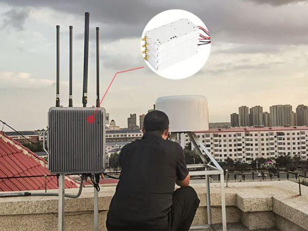
Heilongjiang Weather Center Completes Anti-Drone System Upgrade with Three High-Power Drone Jammer Modules

Tangshan Chem Plant Sealed Drone Gaps With 3 GaN Wideband Modules
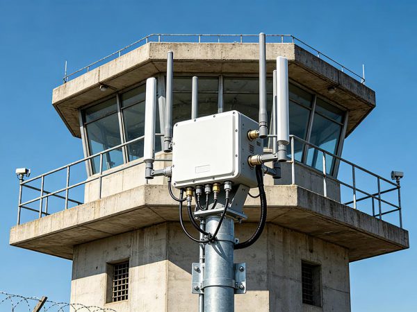
How a National Prison Integrated Our Drone Jamming Module Into Their Fixed Counter-Drone System

Integrating Core RF Power: OEM Drone Jamming Module for Oil Refinery Security | Case Study
Send Us a Message
Related Products
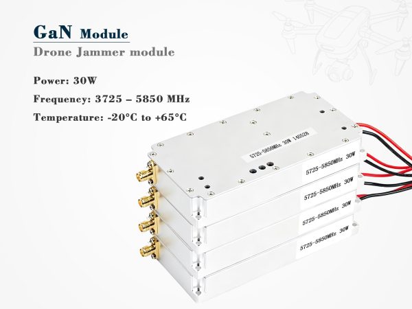
30W 5.8 GHz GaN Drone Jammer Module | 5725–5850 MHz
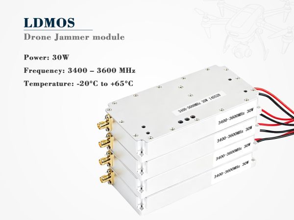
30W LDMOS Jamming Module for 3400–3600 MHz Drone Defense
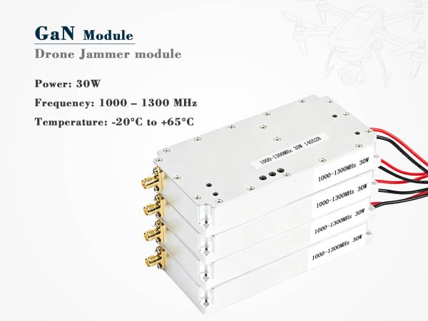
30W Anti-Drone Jamming Module: Compact 1000-1300MHz GaN Solution