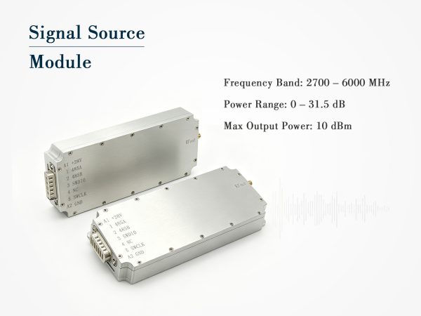
Wideband Signal Source Module – 1000 to 2700MHz, 10dBm with Digital Attenuator
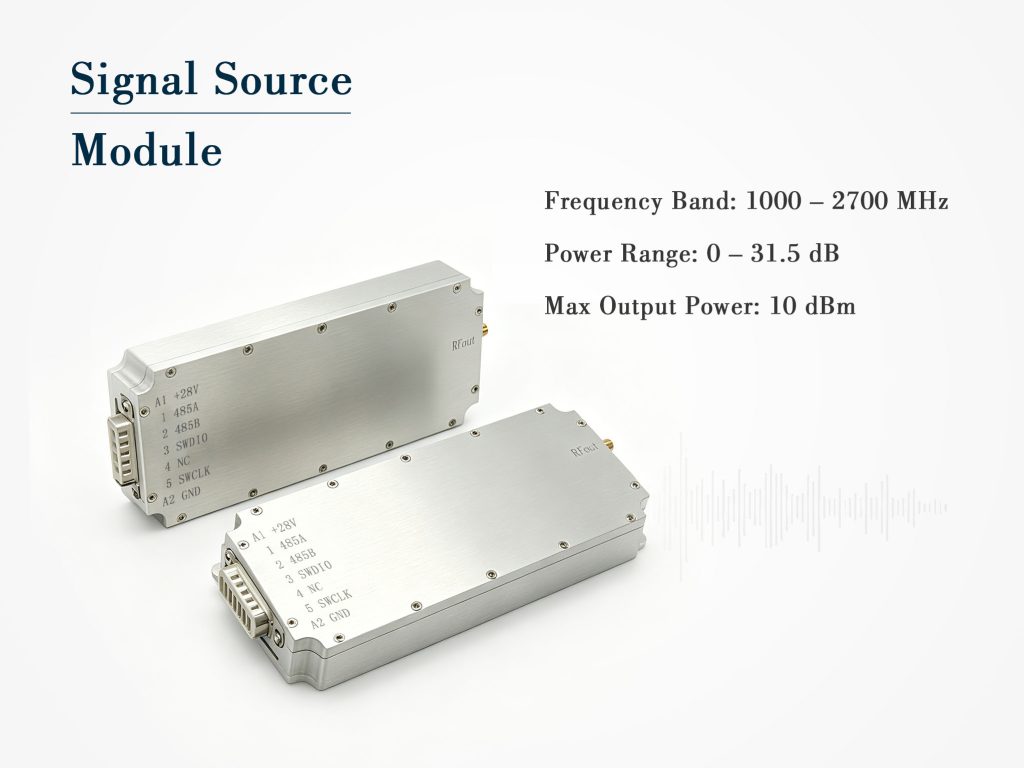
Compact signal source module covering 1000–2700MHz, 10dBm output, 0–31.5dB attenuation (0.5dB step), RS485 control, 24–29V DC, SMA female. Ideal for multi-band test.
Production engineers use this signal source module for fast pass/fail testing of band‑pass filters and LNAs in the 1–2.7GHz region. Radar maintenance teams carry it as a portable reference for checking receiver dynamic range. In R&D labs, it serves as a stable LO for mixer characterisation or as a jammer source for interference tolerance tests. Its RS485 control also makes it easy to integrate into automated Python or LabVIEW test scripts, saving hours of manual adjustment.
Technical Specifications
| Parameter | Typical Value |
| Signal type | Digital signal source |
| Frequency range | 1000~2700MHz |
| Max output power | 10dBm |
| Output VSWR | ≤2.0 |
| Operating voltage | DC24V~29V |
| Max current (28V) | 600mA |
| Attenuation range | 0~31.5dB |
| Attenuation step | 0.5dB |
| Output connector | SMA female |
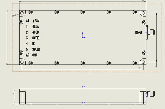
| Power/control connector | 7W2 |
| Control interface | RS485 |
| Dimensions (mm) | 188*98*18.5 |
| Weight | 0.4kg |
Product Details
Overview
This signal source module delivers a stable, clean RF carrier across the entire 1000–2700MHz spectrum. With a fixed +10dBm output and an integrated 0–31.5dB attenuator (0.5dB steps), it gives you precise level control without external components. The module runs on 24–29V DC, consuming 600mA at 28V, and communicates via RS485. Its rugged metal housing and SMA female output make it a drop‑in solution for test benches and embedded systems alike.
Wideband Coverage from 1000 to 2700 MHz
Unlike narrow‑band signal generators, this signal source module covers more than an octave of bandwidth – from 1GHz to 2.7GHz. That includes GPS L1/L2, LTE bands, Wi‑Fi 2.4GHz, and many satellite downlinks. You no longer need separate oscillators for different frequency ranges. Simply set the frequency (fixed internal reference) and use the attenuator to adjust the output. The wide tuning range also supports harmonic and spurious testing of receivers that operate in overlapping bands.
Output Power and Digital Attenuation
The maximum output is +10dBm into a 50Ω load, with a typical VSWR of ≤2.0. This low reflection coefficient ensures accurate power transfer even when the load impedance varies. The built‑in attenuator offers 0 to 31.5dB in half‑decibel increments – a total of 64 steps. Each step is monotonic and repeatable, with settling time under 10µs. This granularity is essential for fine‑tuning sensitivity thresholds and for simulating path loss in fading scenarios. The attenuator is controlled via RS485 commands, and the module returns a confirmation byte for each setting – making this signal source module easy to automate.
Power, Control, and Connectivity
The operating voltage range is 24V to 29V DC, which aligns with standard avionics and industrial power supplies. The 600mA current draw at 28V might seem high, but it is necessary to maintain phase‑noise performance and output stability over the entire 1000–2700MHz range. The 7W2 connector combines DC input and RS485 control signals into one rugged interface – this simplifies cabling in dense rack installations. The RS485 port supports baud rates up to 115200 and allows up to 32 devices on the same bus, each with its own address.
Mechanical Footprint and Thermal Management
Measuring 188×98×18.5mm and weighing 0.4kg, this signal source module is larger than some miniaturised competitors. That extra size, however, provides better heat spreading for the internal regulator and power amplifier. The aluminium housing acts as a heatsink, keeping junction temperatures within safe limits even at high ambient temperatures. The SMA female connector is placed on the short edge for easy access, while the 7W2 connector is on the opposite side – a thoughtful layout that keeps RF and control/power paths separated.
Reliability Under Real‑World Conditions
Extensive testing confirms that the output power varies less than ±0.3dB over a 0°C to 50°C temperature range. The module includes reverse‑polarity protection on the DC input and a self‑resetting fuse for overcurrent events. Additionally, the output stage has built‑in electrostatic discharge (ESD) protection up to 2kV HBM. These features make this signal source module dependable for both lab research and outdoor field operations, where power quality may not be perfectly regulated.
Where This Signal Source Module Excels
Production engineers use this signal source module for fast pass/fail testing of band‑pass filters and LNAs in the 1–2.7GHz region. Radar maintenance teams carry it as a portable reference for checking receiver dynamic range. In R&D labs, it serves as a stable LO for mixer characterisation or as a jammer source for interference tolerance tests. Its RS485 control also makes it easy to integrate into automated Python or LabVIEW test scripts, saving hours of manual adjustment.
Ordering Information
Each unit ships with a matching 7W2 plug, a quick‑start guide, and a detailed command set document. For volume orders, we offer custom options such as extended attenuation (up to 60dB), N‑type connectors, or factory‑set default attenuation values. Firmware can be tailored for proprietary CRC checks or specific polling intervals – just provide your requirements. Standard lead time is 2–3 weeks, with expedited shipping available.
In summary, this signal source module balances wide frequency coverage, precise attenuation, and robust construction. It is not the smallest or lowest‑power device, but it delivers the consistency and durability that professional RF work demands.
Frequently Asked Questions
Case Studies
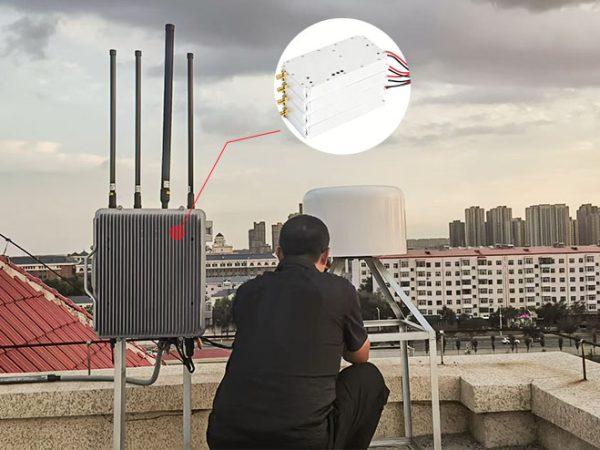
Heilongjiang Weather Center Completes Anti-Drone System Upgrade with Three High-Power Drone Jammer Modules

Tangshan Chem Plant Sealed Drone Gaps With 3 GaN Wideband Modules

How a National Prison Integrated Our Drone Jamming Module Into Their Fixed Counter-Drone System

Integrating Core RF Power: OEM Drone Jamming Module for Oil Refinery Security | Case Study
Send Us a Message
Related Products
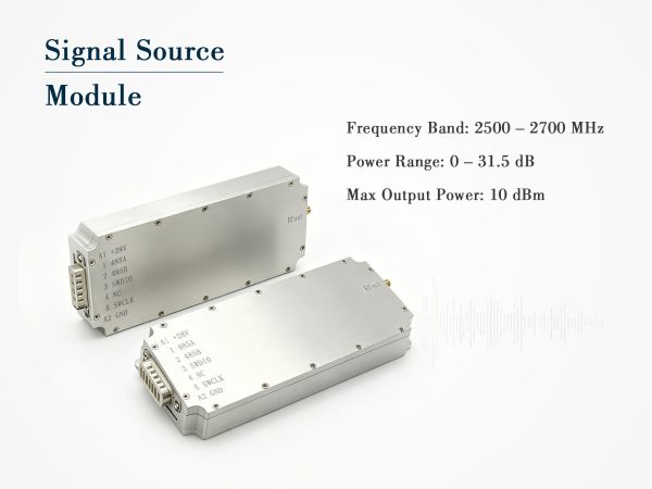
Compact Signal Source Module – 2500–2700MHz, 10dBm with Digital Attenuation
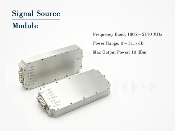
Digital Signal Source Module 1805-2170MHz
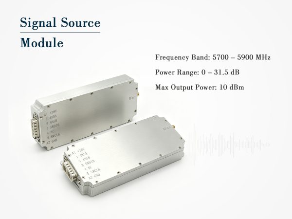
Digital Signal Source Module – 5700–5900MHz, 10dBm